
523. 16.7m x 7m 2-Level House Architectural Floor Plans CAD DWG
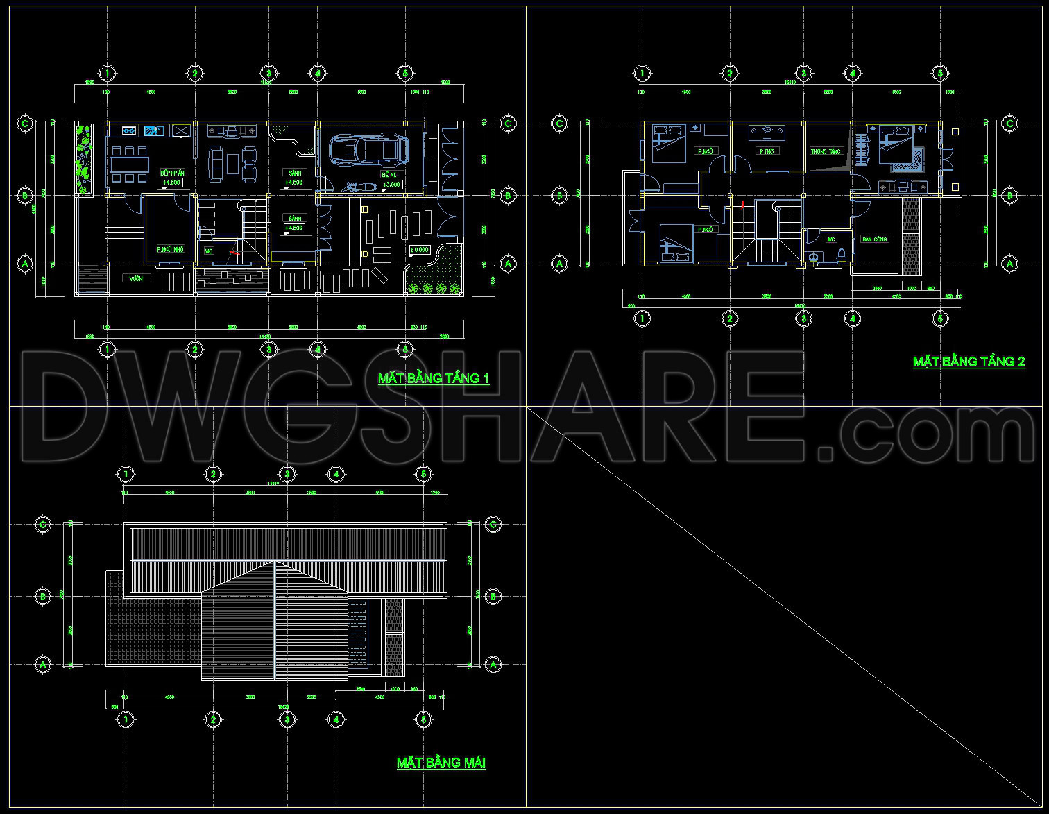
The architectural floor plans for a 16.7m x 7m two-level house provide a comprehensive view of a well-designed residential space. These CAD drawings are meticulously crafted to ensure clarity and functionality in each aspect of the design. As an integral part of architectural documentation, these plans serve multiple purposes from the design phase to construction.
Floor Plan Layout is the backbone of these drawings, showcasing a detailed arrangement of spaces across two levels. This includes spatial arrangements for living areas, bedrooms, and essential utilities, all thoughtfully positioned to maximize the available square footage. These layouts are vital for architects during the design development phase as they allow for precise spatial planning and enable seamless collaboration between different disciplines.
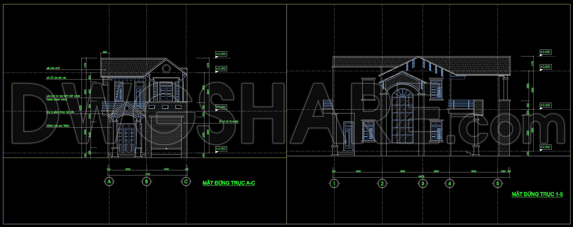
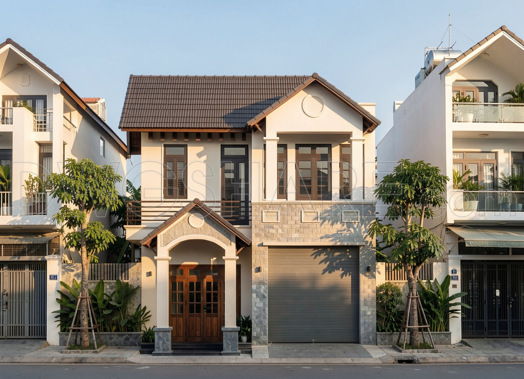
Elevations and Sections reveal the vertical dimensions and relationships within the structure. These drawings are crucial for visualizing the facade and understanding the architectural character of the building. They guide construction teams in implementing elevations accurately, ensuring that exterior finishes and heights align perfectly with the design intent.
The construction detail drawings included in the CAD files are indispensable for ensuring that intricate elements like joinery and material connections are executed with precision. These details prioritise accuracy, aiding construction professionals in avoiding errors, thereby reducing potential costs and delays.
Grid lines, dimensions, and level markers throughout the drawings provide an added layer of clarity. They facilitate easy interpretation and adjustment by architects and engineers, enhancing coordination and integration within the project. The presence of these elements guarantees that discrepancies are minimized, leading to smoother construction processes.
One of the key practical values of these CAD drawings lies in their high technical accuracy and flexibility. Easily modifiable and reusable in AutoCAD, these files not only support ongoing design tweaks but also empower teams to adapt to any site-specific constraints or client requests quickly. This adaptability is a significant advantage in maintaining efficiency and collaboration across project phases.
Additionally, the availability of these CAD DWG files for free enhances their utility as a resource for study and research. Designers can use them as a foundation for developing technical drawings, helping to educate emerging professionals about best practices in architectural design and documentation.
Overall, the 16.7m x 7m two-level house architectural floor plans stand as a testament to precise planning and execution. They serve as a quintessential tool for ensuring that the envisioned design becomes a tangible reality, catering to the diverse needs of architects, designers, and construction teams alike.
I also recommend downloading other Houses CAD drawings for your project reference.
- File format: .DWG
- Size: 353 KB
- Source: DWGshare
- AutoCAD platform 2018 and later versions. For downloading files there is no need to go through the registration process
If you find our work useful, your support would mean a lot and help us grow even better.DONATE
Related posts
325. CAD design drawings for a 3-story townhouse with dimensions of 4.6m x 17.5m
2 Levels Classic Villa 11.3×17.5m AutoCAD File Free Download
498. Download CAD Design Drawings for a 3-Story House with Dimensions 3.6m x 16m
3-Story Classic Villa Sections Details AutoCAD File 16.5x19m
Structural Drawings Of 2-Story House A Complete Project 10.5x12m For Download
390. Download CAD Design Drawings for a 3-Story House with Dimensions 13.7m x 14.7m
Flat House 2D Drawing Free Download
559. Luxury Classic Villa 18 × 12 m – 3-Story Architectural Drawings
452. 3-Story Modern House 5m × 20m – Architectural Floor Plans, Elevations & Sections