

528. 3-Story Residential House – 4.1m × 12m CAD DWG
The 3-story residential house with dimensions of 4.1m × 12m offers a distinctive example of compact urban living, represented through detailed architectural drawings in CAD DWG format. These drawings are crucial tools in the design and construction process, providing a detailed visual guide to both the conceptual and practical aspects of the project.
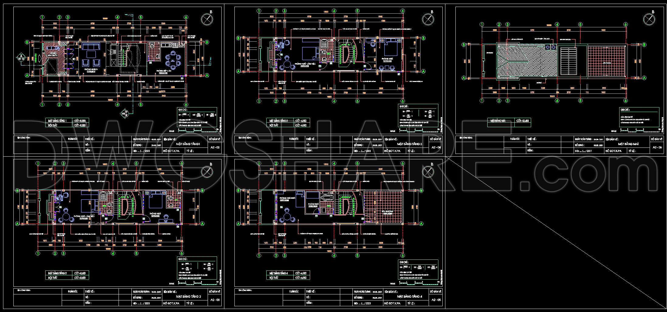
Starting with the architectural floor plans, these drawings reveal a meticulously engineered layout. They outline each floor’s design, emphasizing how the architectural team efficiently utilizes the restricted space. The floor plans highlight key components such as living areas, bedrooms, and service spaces. The compact yet functional arrangement maximizes usable space while maintaining a comfortable living environment. Architects and designers can use these floor plans to explore various layout scenarios during the design development phase.
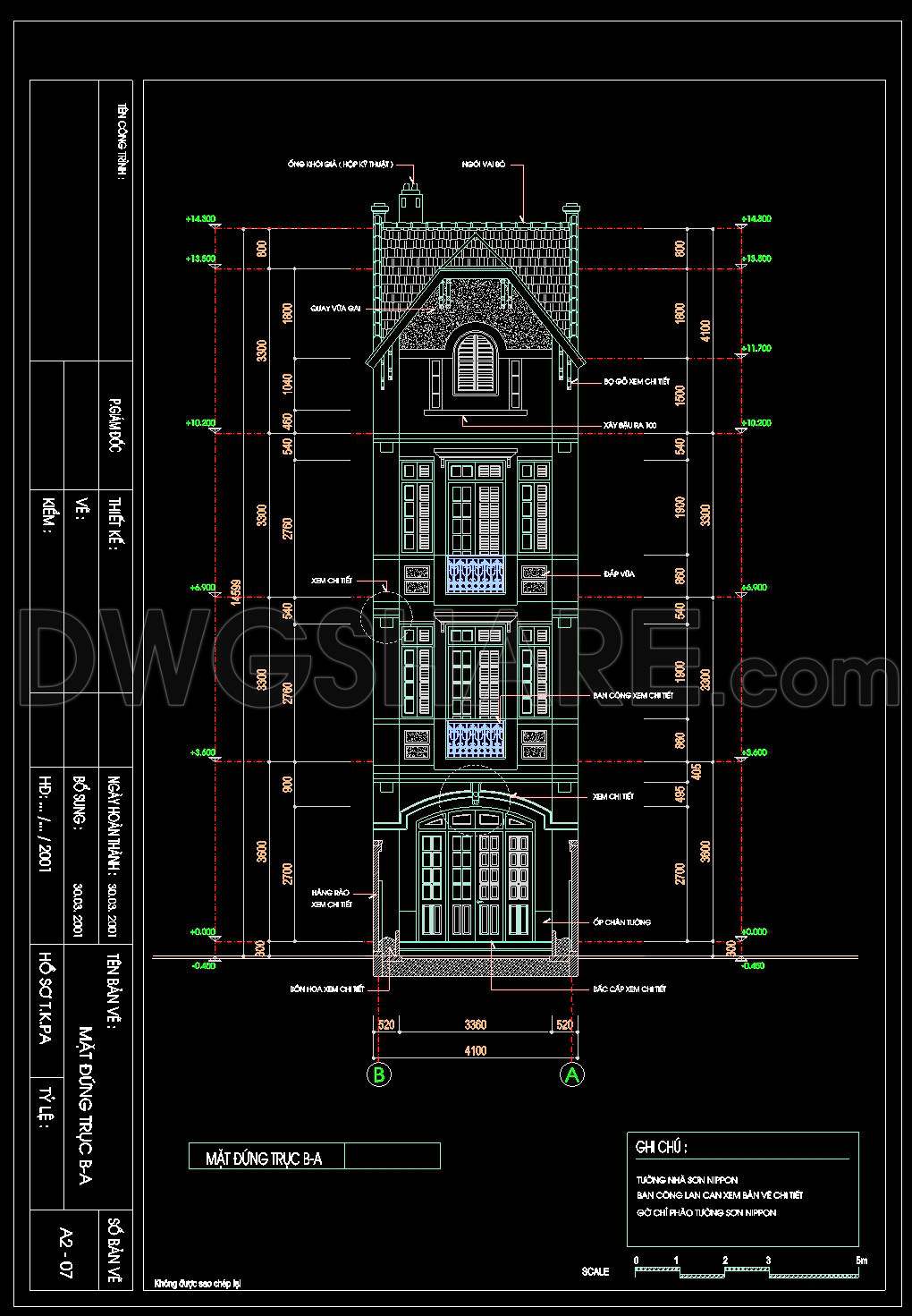
The elevations and sections included in this set provide insightful details into the house’s exterior and interior aspects. These drawings are essential for visualizing the facade treatment, window placements, and roof design. Each elevation is precisely dimensioned, reflecting aspects like the alignment and type of openings, cladding materials, and decorative elements. Sections cut through the structure at strategic locations to reveal heights, construction layers, and interior spatial relationships. Elevations and sections are invaluable for design presentations and ensuring compliance with building regulations.
Accompanying these are construction detail drawings, which offer intricate insights into building elements, such as structural connections, roofing details, and wall assemblies. These details are crucial for construction teams, providing exact specifications required to achieve the intended structural and aesthetic outcomes. Grid lines, dimensions, and level markers are present for precise execution on-site.
The benefits of these AutoCAD drawings include their technical accuracy and ease of modification. Architects and contractors can quickly adapt these files for site-specific requirements or design variations. This efficiency aids in reducing potential errors and optimizing project costs through enhanced design-construction coordination.
These CAD DWG files are freely available, making them an excellent resource for design reference, study and research, or as a base for technical drawing development. Sharing these files supports collaborative efforts and knowledge exchange within the architecture and construction industries.
I also recommend downloading other CAD drawings for your project reference.
- File format: .DWG
- Size: 1 MB
- Source: DWGshare
- AutoCAD platform 2018 and later versions. For downloading files there is no need to go through the registration process
If you find our work useful, your support would mean a lot and help us grow even better.DONATE
Related posts
Apartment Plans AutoCAD File Free Download
617. 2-Story Modern House 15 × 16 m – Floor Plans & Elevation CAD Drawing
847. Free Download Architectural Floor Layout Plans for a 3-Storey Townhouse
137. Free Download Electrical Design Drawings for a 5-Story Townhouse
824. Download free 1-story villa CAD drawing featuring 3 bedrooms and an island kitchen
3-Story Classic Villa Sections Details AutoCAD File 12.3×16.7m
Bunglow Layout Plan and Elevation AutoCAD File Free Download
307. CAD design drawings for a 4-story townhouse with dimensions of 4.1m x 16m
302. CAD design drawings for a 3-story townhouse with dimensions of 7m x 17m