
739. Standard Skin Reinforcement Details CAD Drawings DWG
The Standard Skin Reinforcement Details CAD Drawings provide an essential resource for architects and construction professionals engaged in structural design and implementation. These structural drawings are particularly focused on the reinforcement of concrete elements to ensure structural integrity and compliance with engineering standards.
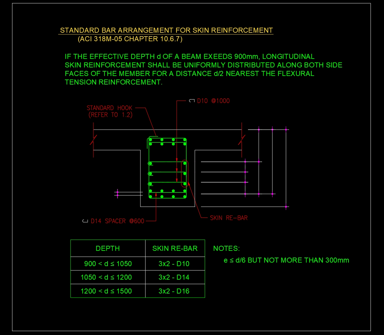
In the image, the reinforcement details outline the standard arrangement for skin reinforcement. The details clearly depict how longitudinal skin reinforcement should be uniformly distributed along both side faces of a concrete beam, particularly where the effective depth exceeds 900mm. The layout is designed for a distance of d/2, where ‘d’ represents the effective depth of the beam, to enhance flexural tension reinforcement.
The drawing includes critical elements such as:
Uniform bar arrangement
Detailed spacing and arrangement of hooks (denoted as D10 @1000)
Skin re-bars at different depths (900 < d ≤ 1500)
The table within the drawing provides clear specifications for depth categories and associated skin re-bar sizes, including D10, D14, and D16 specifications with corresponding spaces. This precise detailing plays a crucial role in guiding how reinforcement should be installed on-site, ensuring consistency with design intentions and safety regulations.
For architects, these CAD drawings serve as a vital component during the design development phase by guiding technical specifications that meet structural requirements. Interior designers may reference these details when integrating structural elements into comprehensive interior schemes, ensuring seamless coordination between aesthetic and structural elements. Construction teams use these drawings for precise on-site implementation, promoting efficient coordination and minimizing errors or miscommunications.
The practical value of these CAD drawings includes:
High technical accuracy
Ease of modification and reuse within AutoCAD
Enhanced coordination between design and construction phases
Reduced potential for errors, leading to cost optimization
These CAD DWG files are freely shared for professional use, making them an ideal reference for design practitioners or students involved in study and research. These files can also serve as a reliable base for further development of technical drawings.
I also recommend downloading other Structural Details drawings for your project reference.
- File format: .DWG
- Size: 36 KB
- Source: DWGshare
- AutoCAD platform 2018 and later versions. For downloading files there is no need to go through the registration process
If you find our work useful, your support would mean a lot and help us grow even better.DONATE
Related posts
449. Download Reinforced Concrete Beam Reinforcement CAD Drawings with Rebar Schedules (DWG)
209. CAD drawing Of Village Reinforced Concrete Details Free download
198. CAD drawing Of Culvert at frontage road Free download
361. Free Download of Structural CAD Drawings for 8.7m x 13.2m Reinforced Concrete Townhouse
19.Gym Hall Steel Roof Details CAD
610. Free Download CAD Details for Bridge Columns and Plinth Beams
20.Steel Truss Bridge Cross Section CAD
607. Free DWG CAD Template for Bored Pile Construction Method
308. Download free CAD structural drawings for a 4.5m x 15.7m reinforced concrete townhouse construction