
744. Steel Truss Details CAD Drawing – Free DWG Download
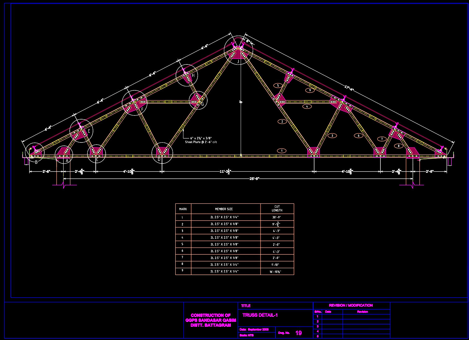
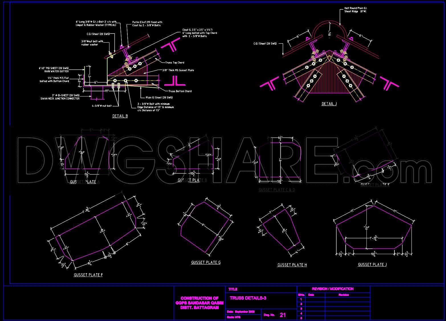
The Steel Truss Details CAD Drawing offers an intricate look into the structural mechanics of truss systems, essential for architects and engineers focused on designing robust frameworks. These structural drawings provide comprehensive insights crucial for both the implementation phase and academic study. Key elements featured comprise a combination of detail drawings, sections, and connection specifications, all meticulously plotted within a DWG file format.
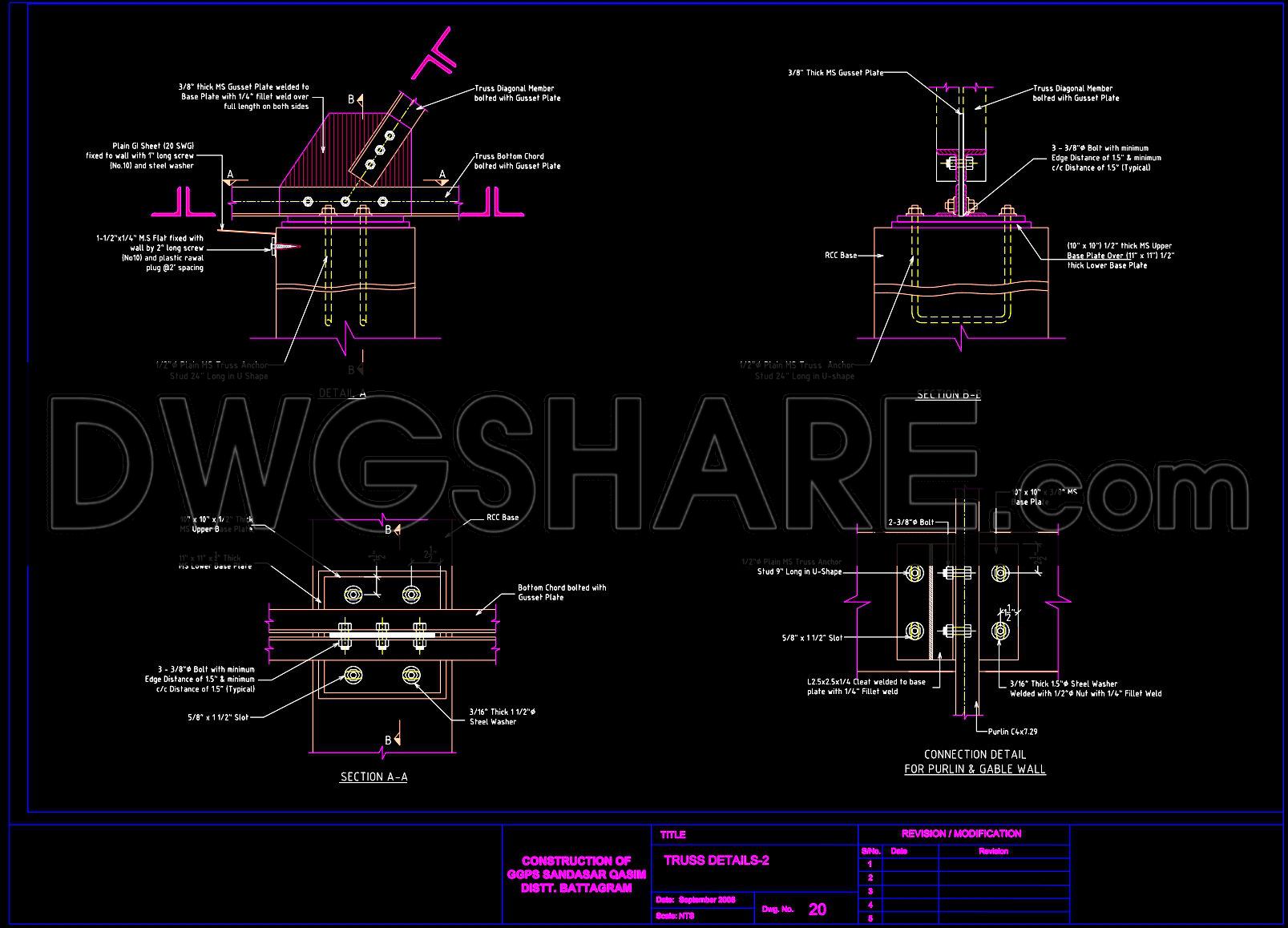
To begin with, the primary focus of the drawings is on the steel truss components which include but are not limited to gusset plates, truss top chords, bottom chords, purlin connections, and base connections. Each component is detailed with dimensions and annotations that highlight the materials used, such as various thicknesses of MS gusset plates and steel washers, bolting patterns, and welding specifications.
Sections A-A and B-B serve as cutaway views, showcasing the cross-sectional composition of the truss elements. Details such as the arrangement of bolts and the integration of gusset plates illustrate how these components work in unison to maintain structural integrity. Such details are imperative to ensuring that structural loads are aptly supported and distributed across the framework, minimizing the potential for stress concentrations that could lead to structural failures.
The truss details are crucial for architects during the design development phase, allowing them to calculate load paths and establish a solid partnership with structural engineers to optimize material usage and cost-effectiveness. Interior designers may refer to these technical specifications when integrating overhead designs into larger spatial concepts, ensuring aesthetic and practical cohesion with the overall design scheme.
Construction teams will find the drawings invaluable for site referencing. They provide clear guidelines for assembling components, verifying connections, and coordinating with other trades to reduce errors and overlap during the on-site installation of steel structures. The accuracy and clarity of these CAD drawings offer the advantage of easy modifications within AutoCAD, thus enabling seamless adjustments tailored to project-specific requirements.
The availability of these CAD DWG files for free makes them ideal for design reference, academic research, and as a foundation for further technical drawing developments, allowing practitioners and students alike to explore structural dynamics practically.
I also recommend downloading other Structural Details drawings for your project reference.
- File format: .DWG
- Size: 270 KB
- Source: DWGshare
- AutoCAD platform 2018 and later versions. For downloading files there is no need to go through the registration process
If you find our work useful, your support would mean a lot and help us grow even better.DONATE
Related posts
301. Structural Drawings Of 3-Story House A Complete Project 5m x 20m For Download
150. Cad Drawing Of Tower Crane Raft Foundation Details For Download
257. Structural Drawings Of 3-Story House A Complete Project 4m x 18m For Download
104.Autocad Drawing Of Deck Ramp Reinforced Concrete Details For Download
48.Overhead Crane Structural Details CAD
283. Structural Drawings Of 3-Story House A Complete Project 5m x 14.6m For Download
18.Colosseum Steel Roof Elevation and Sections Details CAD
704. Free Download Pre-Tension Beam Reinforcement Details CAD
25.Gantry Grab Bucket Elevation and Section Details CAD