
746. Stilling Basin Concrete Layout & Cross Sections – Free DWG Download
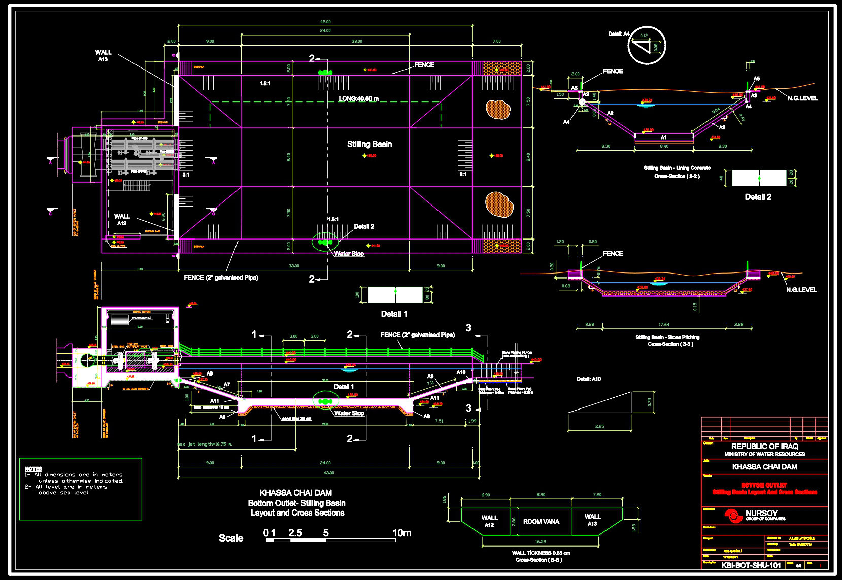
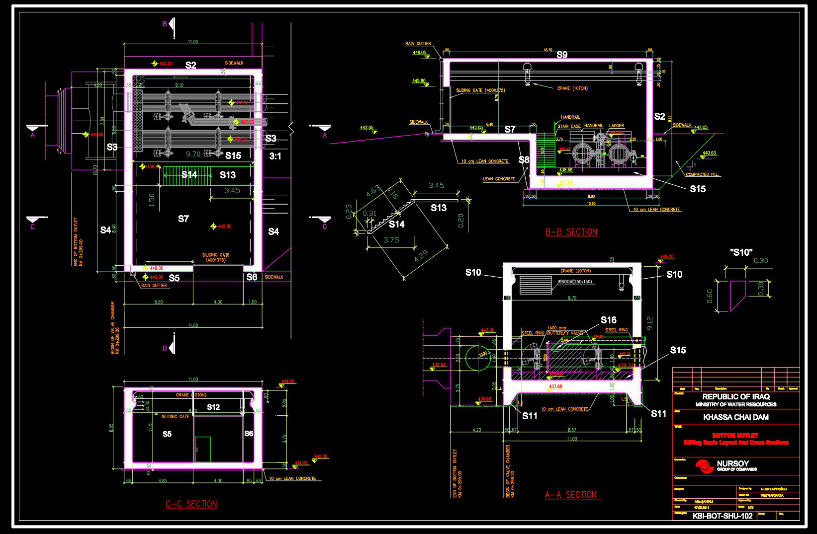
The Stilling Basin Concrete Layout & Cross Sections CAD drawings provide a comprehensive view of the structural intricacies involved in the construction of stilling basins for water management systems. These structural drawings are crucial for accurately envisioning how the components fit together and ensuring efficient construction practices.
The first drawing emphasizes the layout and sectional views which includes critical elements such as:
Functional floor plan layout – This provides an overhead view of the stilling basin, showcasing dimensions and the precise location of components, essential for initial design and layout planning.
Elevations and sections – These views offer detailed insights into the vertical arrangement of different sections, including wall heights and the basin depth.
Construction detail drawings – Specific areas such as the sliding gate, crane positions, and drainage systems are meticulously detailed for precise construction implementation.
Grid lines, dimensions, and level markers – Essential for accurate measurement and ensuring all components are aligned correctly during the build process.
These drawings are indispensable in real construction practice. Architects use them to advance the design phase, verifying each component’s compatibility with the overall structure. Interior designers might not frequently use this type of drawing, but the technical details can inform related infrastructure projects. For construction teams, these drawings act as blueprints, guiding every stage of building with precision, and minimizing errors.
The practical value of these CAD drawings lies in their high technical accuracy. Being CAD-based, they allow for easy modification and reuse, making adjustments swift and efficient in programs like AutoCAD. This results in improved coordination between design and construction teams, ultimately reducing errors and optimizing costs.
The value extends to the fact that these CAD DWG files are freely available. They offer excellent resources for design reference, study, and research, or as a foundational base for further technical drawing development.
I also recommend downloading other Structural Details drawings for your project reference.
- File format: .DWG
- Size: 1 MB
- Source: DWGshare
- AutoCAD platform 2018 and later versions. For downloading files there is no need to go through the registration process
If you find our work useful, your support would mean a lot and help us grow even better.DONATE
Related posts
272. Structural Drawings Of 3-Story House A Complete Project 9m x 14.5m For Download
699. Free Download Pile and Raft Reinforcement CAD Drawing
405. Free Download of Structural CAD Drawings for 7.5m x 13.7m Reinforced Concrete Townhouse
627. Free Download Detailed Concrete Column CAD Drawings
354. Free Download of Structural CAD Drawings for 9.8m x 13m Reinforced Concrete Townhouse
194. CAD drawing Of Boring Log Template Free download
49.Hanging Conveyor Belt Structural Details CAD
243. Structural Drawings Of 5-Story House A Complete Project 4.8m x 13.6m For Download
87.Autocad Drawings Of Details Of Valves Chambers For Download