
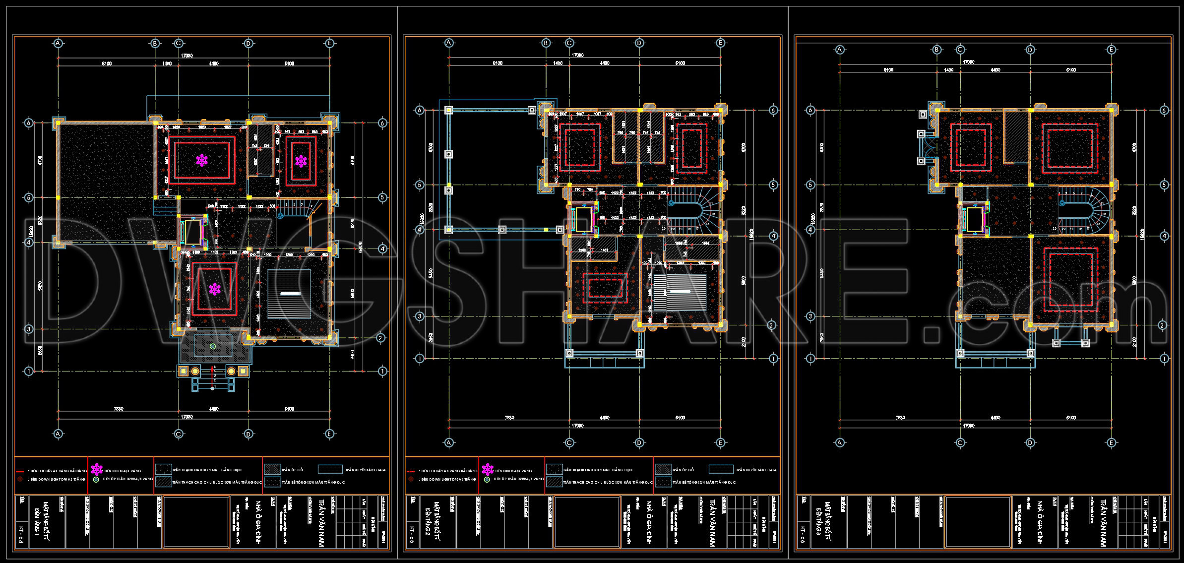
212. Residential Reflected Ceiling Plan & Lighting Layout CAD Drawings (DWG)
The Residential Reflected Ceiling Plan & Lighting Layout CAD drawings showcased above represent a crucial component in architectural documentation, specifically focusing on reflected ceiling plans and lighting layouts. These drawings are essential for ensuring the seamless integration of aesthetics and functionality within residential spaces. By providing a detailed view from below, they illustrate not only the ceiling finishes but also the precise positioning of lighting fixtures, contributing significantly to design precision and execution accuracy.
The reflected ceiling plan is instrumental in conveying numerous elements including ceiling heights, lighting fixtures, and ventilation systems. Architects rely on these plans to align design intentions with practical installations. The provision of grid lines and dimensions allows for an exact understanding of spatial relationships and fixture placements, ensuring that transitions between different ceiling elements are handled smoothly. For architectural development, these plans serve a double role—first in client presentations, displaying the intended atmosphere of illuminated spaces, and second in technical detailing, guiding construction teams on precise cuts and fittings.
Moreover, lighting layouts depicted in these CAD drawings are crafted to ensure optimal distribution of light, enhancing both the aesthetic and functional quality of interior spaces. These layouts specify the type and position of each light source, thereby allowing designers and contractors to foresee illumination patterns and design accordingly. Interior designers benefit by utilizing these plans to create environments that are not only visually appealing but also compliant with required standards of light distribution and energy efficiency.
CAD Drawings hold a significant advantage due to their high technical accuracy and versatility. They can be easily modified or reused in AutoCAD software, promoting flexibility and efficiency in design processes. For construction teams, these accurate layouts substantially reduce errors and facilitate cost optimization by providing clear and precise instructions, crucial for effective coordination. The use of these detailed plans minimizes the risk of miscommunication and facilitates smooth, hassle-free installations.
Shared freely, these CAD DWG files are valuable resources for design references, study, and as bases for evolving technical drawing developments. They offer an excellent opportunity for architects, students, and professionals to explore, understand, and implement effective design solutions within residential projects.
I also recommend downloading other Ceiling CAD drawings for your project reference.
- File format: .DWG
- Size: 321 KB
- Source: DWGshare
- AutoCAD platform 2018 and later versions. For downloading files there is no need to go through the registration process
If you find our work useful, your support would mean a lot and help us grow even better.DONATE
Related posts
72. Detailed CAD design drawings for the water supply system in a 3-story townhouse
91. CAD drawings detailing the design of water supply and drainage systems for a 3-story townhouse
293. 2-Story House Plumbing Plans – Water Supply & Drainage System DWG
101. Detailed CAD drawings for the ceiling layout design of a 2-story townhouse
92. Detailed CAD drawings for the ceiling layout design of a 3-story townhouse
180. Free Download of Detailed Technical CAD Drawings for Track Light Installation
230. Villa Electrical & Lighting CAD Drawings
209. Water Supply & Drainage CAD Drawings for Apartment Building (DWG)
16.Free Autocad Ceiling Details