
218. Complete House Electrical CAD Drawings – Lighting, Power & Electrical Systems
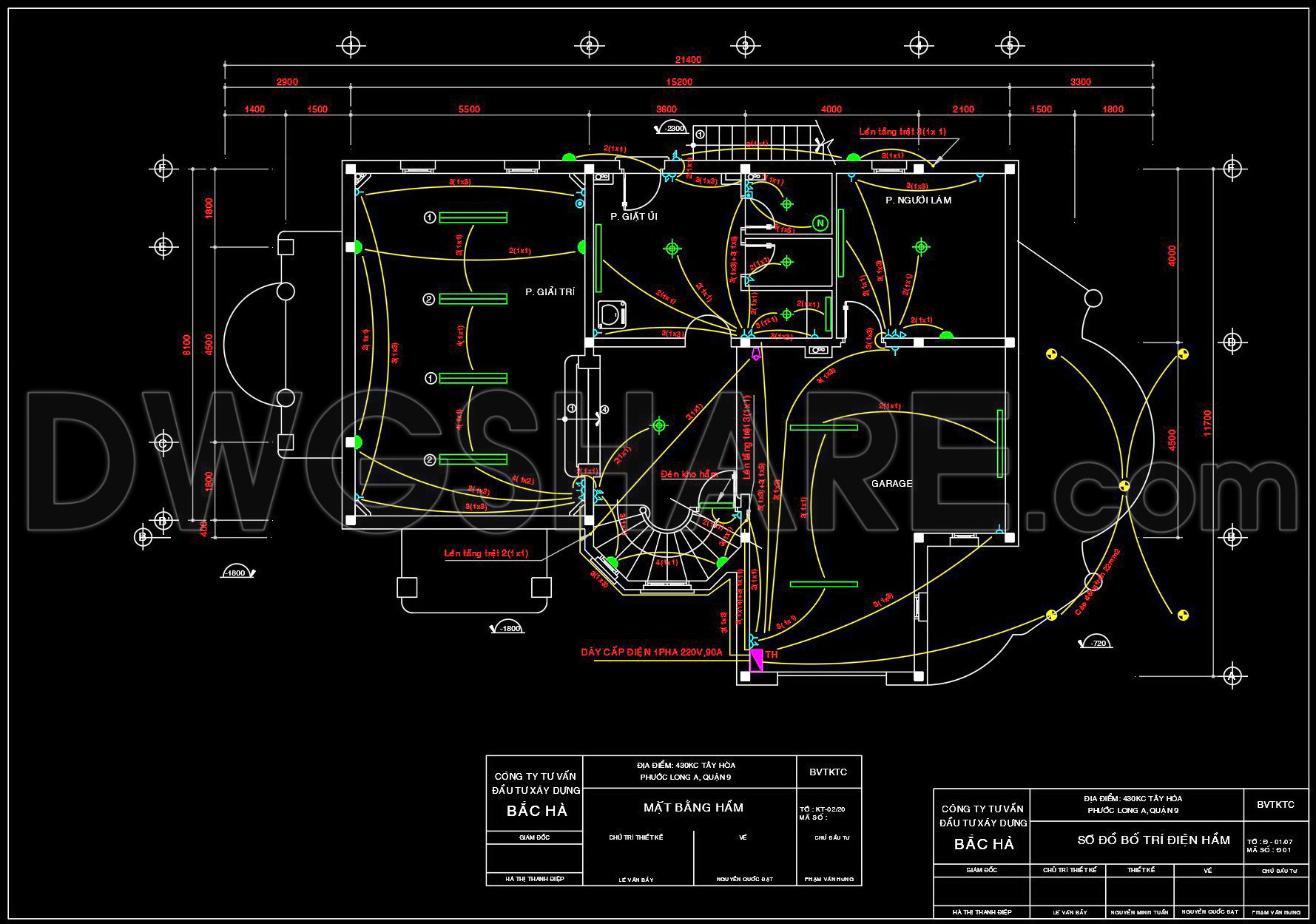
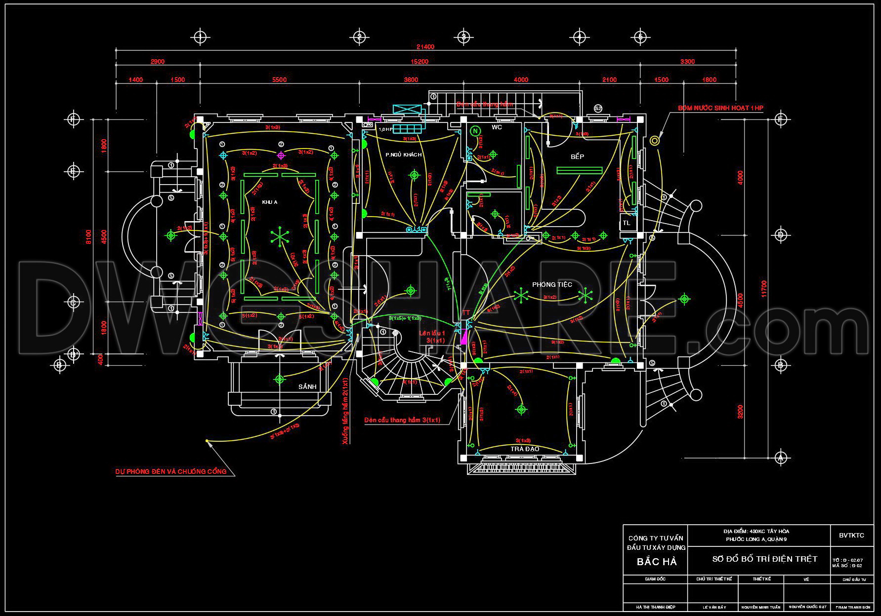
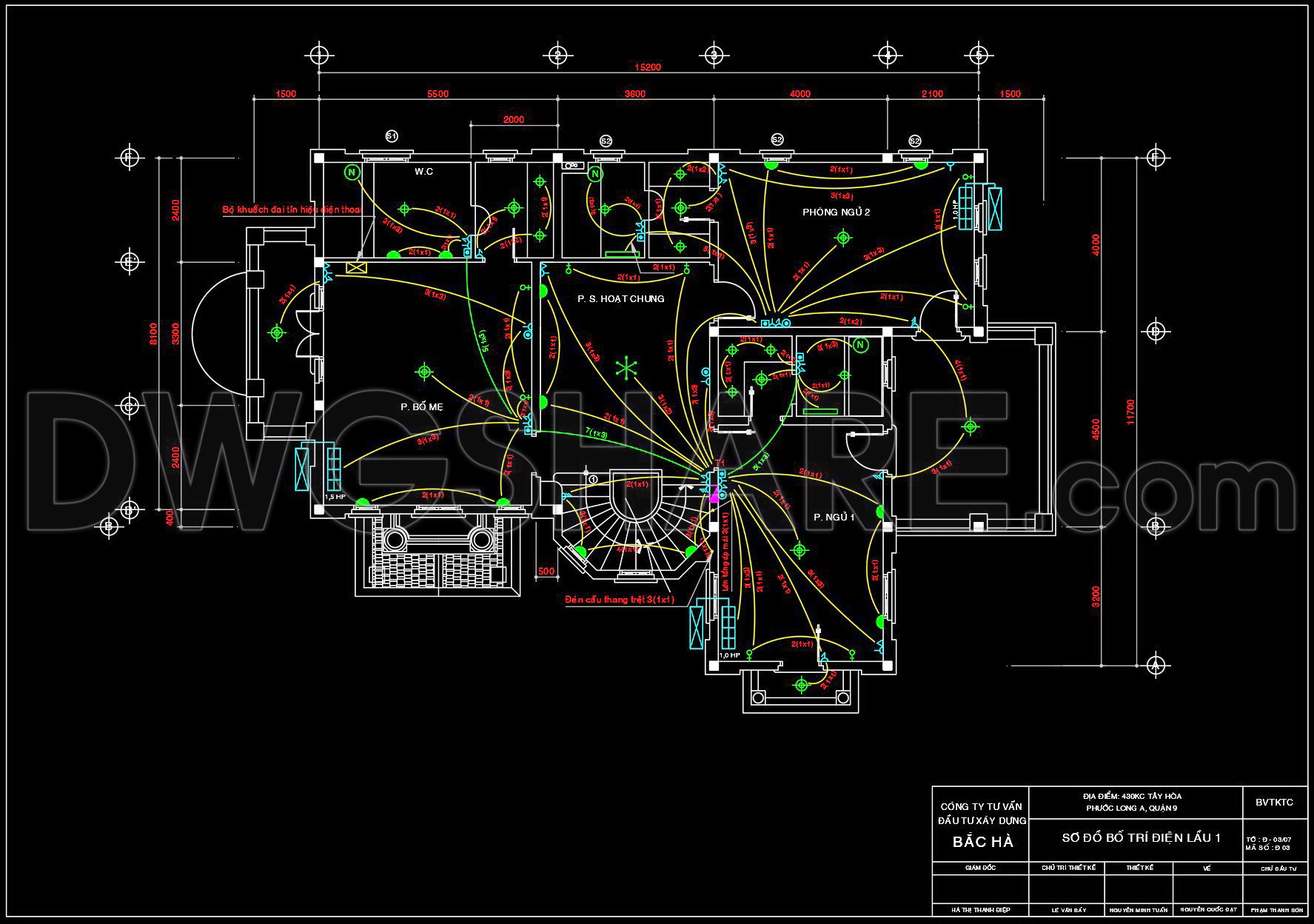
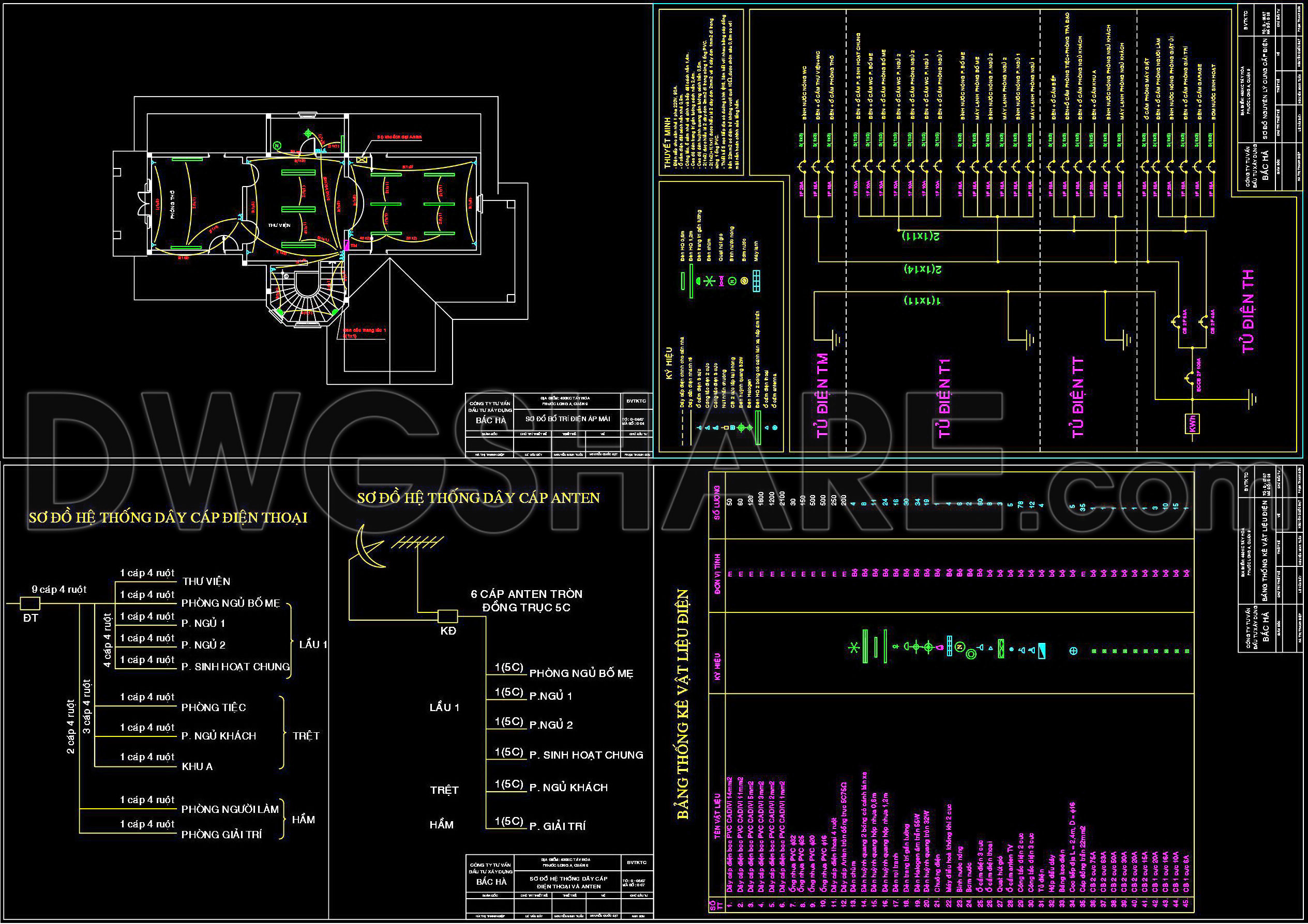
The CAD drawings provided focus on complete house electrical systems, encapsulating the intricacies of lighting, power, and electrical layouts. This technical documentation is essential for architects, interior designers, and construction professionals as they offer a comprehensive guide to planning and implementation.
Beginning with the architectural floor plans, these CAD drawings meticulously outline the electrical layout. They include precise dimensions, with grid lines and level markers clearly annotated, ensuring that each electrical component aligns perfectly within the architectural design. The functional layout indicates the positioning of power outlets, switches, and lighting fixtures, which are integral to creating an efficient and safe living environment.
A key aspect of these drawings is the inclusion of elevations and sections that provide detailed visual insights into the vertical relationships of electrical elements. This ensures that all installations adhere to height regulations and are optimally placed for ease of access and functionality. Such sections are vital for anticipating potential clashes and resolving them prior to actual construction, thus optimizing installation time and expense.
Furthermore, the detailed component schema showcases the intricate wiring paths and connections, demonstrating how each element interacts with the overall power system. For professionals, the visual representation of wiring paths reduces the likelihood of error during installation, allowing for swift and reliable implementation. Essential technical features like the type and capacity of wiring and network cables are also visualized, complementing the seamless design and encouraging superior functionality.
The utility of these CAD drawings extends beyond mere visualization. Their high technical accuracy and versatility in AutoCAD ensure they can be efficiently modified or reused across multiple projects. This adaptability streamlines the design process, facilitates coordination between architects and builders, and significantly reduces construction errors. Ultimately, such precision in planning leads to cost reductions and improved project outcomes.
These CAD DWG files, shared for free, serve as valuable resources for design reference, study, and research. Professionals can confidently use them as a base for further technical drawing development, ensuring that every electrical component aligns with overarching design objectives to create cohesive and efficient house electrical systems.
I also recommend downloading other Mechanical, Electrical CAD drawings for your project reference.
- File format: .DWG
- Size: 241 KB
- Source: DWGshare
- AutoCAD platform 2018 and later versions. For downloading files there is no need to go through the registration process
If you find our work useful, your support would mean a lot and help us grow even better.DONATE
Related posts
300. Free Download 4-Story Residential House Water & Drainage CAD Drawings
219. Download Complete Plumbing CAD Drawings for House – Water Supply & Drainage
246. 3-Story Modern House Plumbing & Drainage CAD Drawings
348. Complete Plumbing Construction Drawings for Commercial Building
145. CAD drawings detailing the design of water supply and drainage systems for a 3-story townhouse
75. CAD drawings for detailed electrical designs for a 4-story townhouse
178. Complete Water Supply and Drainage CAD Drawings for House
273. Complete House Plumbing Plans – Water Supply & Drainage DWG
29.Village Electrical Scheme Details CAD