
238. Complete 2-Story House MEP & Plumbing CAD Drawings
The Complete 2-Story House MEP & Plumbing CAD Drawings offer a comprehensive set of technical documents that are indispensable for anyone involved in architectural and construction projects. These drawings are a crucial resource for architects, interior designers, and construction teams seeking to ensure the seamless implementation of mechanical, electrical, and plumbing (MEP) systems in a two-story residential building.
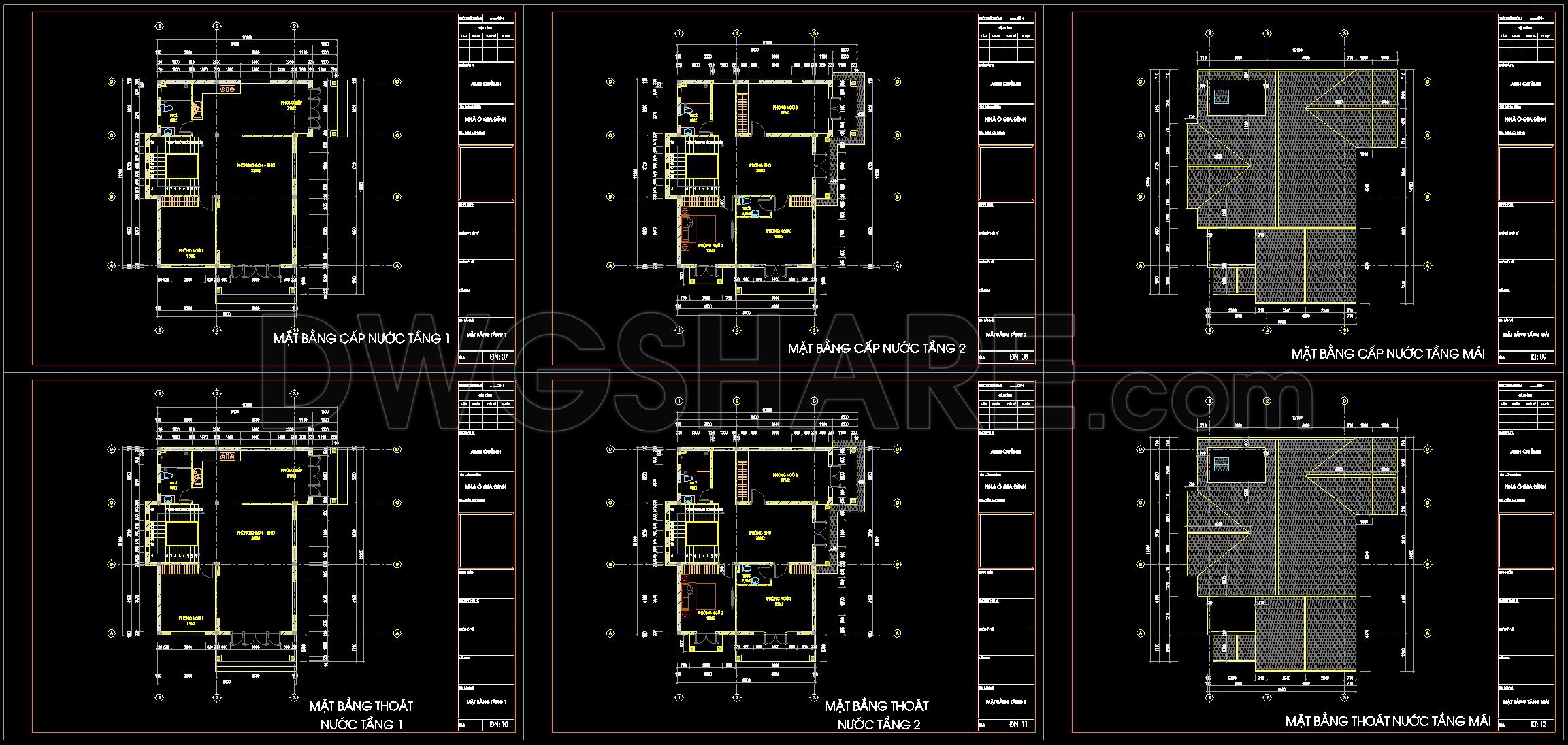
Starting with the MEP floor plans, these drawings showcase detailed layouts for each level. The plans meticulously mark out essential components such as pipes, ducts, and electrical circuits. These elements are vital for designing efficient systems that align with the structural layout of the building. The plans encompass specific sections for both the first and second floors, providing a clear overview of water supply lines, drainage systems, and electrical distributions crucial for the building’s functionality.
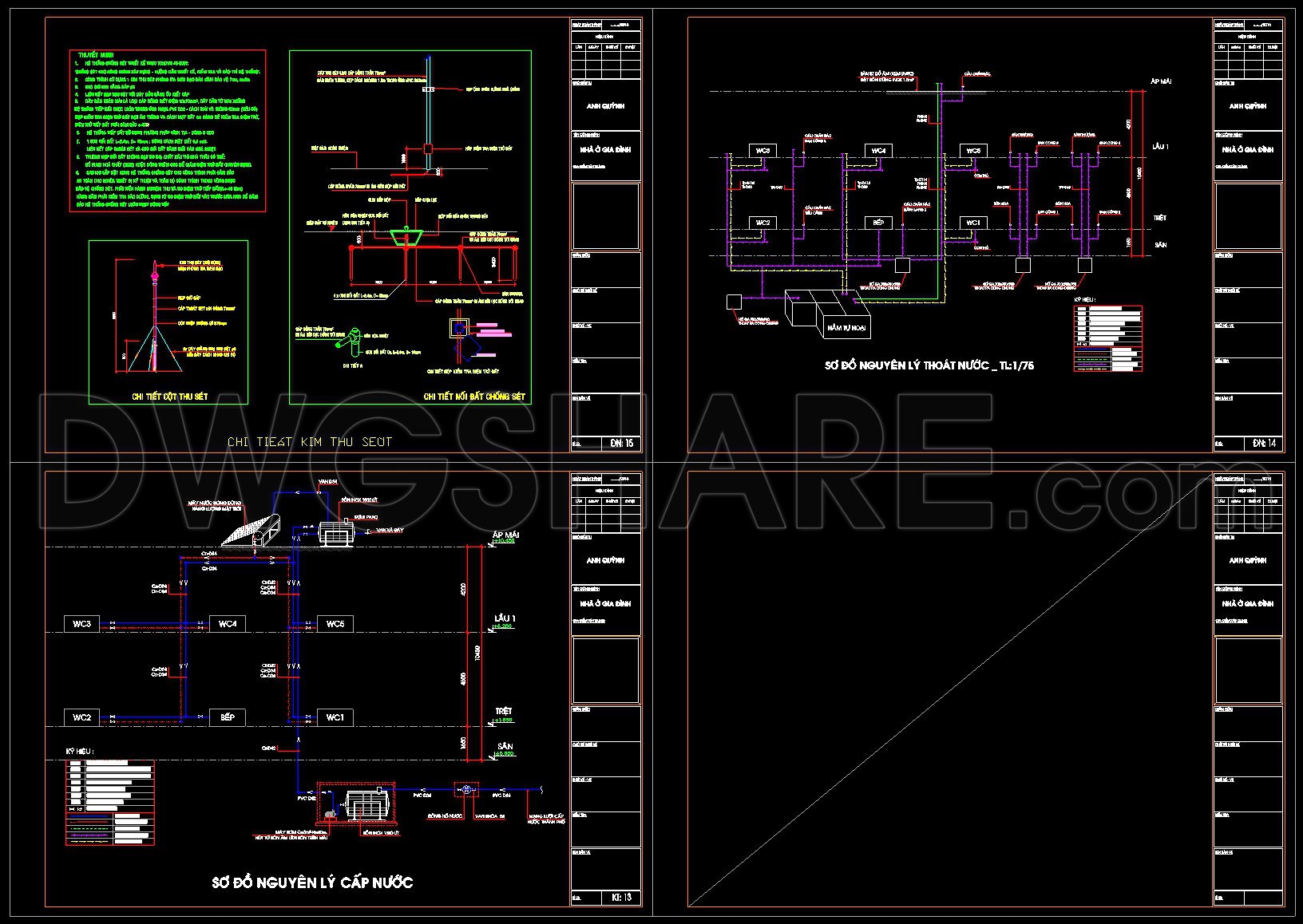
Furthermore, the plumbing drawings highlight the water supply and drainage configurations. They illustrate how the water systems are integrated into the house’s structure, showing connections to various utility areas such as kitchens and bathrooms. The clear depiction of these systems helps in planning efficient water flow and pressure management, which is fundamental for ensuring reliable water access and waste disposal.
The inclusion of detailed section drawings and schematic diagrams aids in understanding the vertical relationships between different system components. Using these sections, professionals can visualize how systems like HVAC and plumbing are routed through spaces, ensuring proper coordination and avoiding spatial conflicts. This is particularly beneficial during the construction phase, where precise installation reduces the risk of costly modifications.
Key features like grid lines, dimensions, and level markers are prominently displayed, assisting architects and engineers in maintaining alignment and accuracy throughout the design and construction processes. These technical markers ensure that all parties involved have a common reference, reducing errors and streamlining communication between teams.
The practical benefits of these CAD drawings are numerous. They are known for their high technical accuracy, ease of modification in AutoCAD, and applicability in both initial design phases and later construction stages. By offering a clear and detailed presentation of MEP systems, these drawings facilitate improved coordination between design and construction, ultimately aiding in cost optimization and reducing the likelihood of errors during construction.
These CAD DWG files are freely available, making them an excellent resource for design reference, academic study, and as a foundational base for developing further technical drawings. Their availability ensures that both students and professionals can benefit from high-quality design documentation without financial barriers.
I also recommend downloading other Houses CAD drawings for your project reference.
- File format: .DWG
- Size: 403 KB
- Source: DWGshare
- AutoCAD platform 2018 and later versions. For downloading files there is no need to go through the registration process
If you find our work useful, your support would mean a lot and help us grow even better.DONATE
Related posts
324. Complete CCTV, LAN Network and Public Address System CAD Drawings DWG
116. CAD drawings for detailed electrical designs for a 3-story townhouse
9.Electric Lighting Symbols CAD Blocks
21.Lighting Pole Foundation and Electrical Details CAD
504. CAD Drawings Detailing the Design of Water Supply and Drainage Systems for a 3-Story Townhouse
14.Guard Room Lighting and Power Plan CAD
74. CAD drawings detailing the design of water supply and drainage systems for a 3-story townhouse
368. Classical Villa Elevation CAD Drawing – Lightning Protection System Design
220. Complete MEP CAD Drawings for 3-Story Luxury Villa – Electrical, Water Supply & Drainage