
285. Residential Water Supply & Drainage Plans – Plumbing System Layout DWG
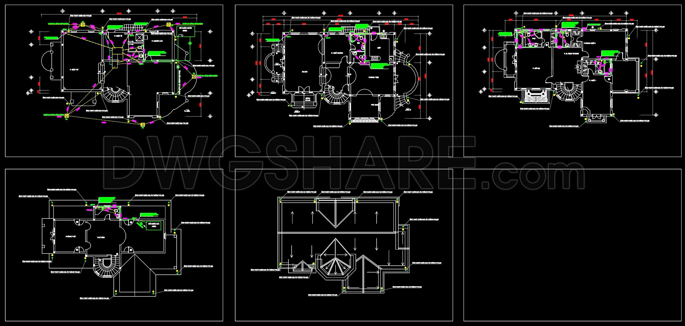
The Residential Water Supply & Drainage Plans are a crucial component of the plumbing system layout provided in the comprehensive CAD DWG files. These drawings are meticulously structured to facilitate the integration of water supply and drainage systems within residential architecture. The emphasis is placed on accuracy and utility, ensuring these plans are a valuable resource for architects, engineers, and construction professionals engaging in design development and building execution.
Starting with the plumbing system layout, these drawings present a complete overview of both supply and drainage routes, clearly delineating the intricate network essential for efficient water management. Key elements featured in these DWG files include:
Functional floor plan layout: The plan outlines the strategic placement of pipes and connections that serve various residential spaces, ensuring a seamless water supply chain across the property.
Grid lines, dimensions, and level markers: These features provide precise measurements and reference points crucial for proper installation and system integration, allowing for high-fidelity execution during construction phases.
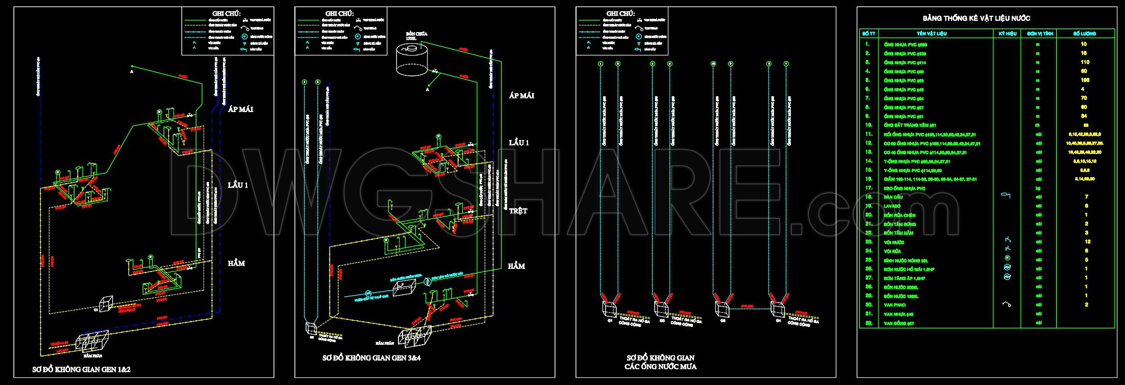
Detailed piping layouts: With marked specifications for materials such as PVC, the drawings highlight essential components like joints, valves, and fittings, which are instrumental in the construction and maintenance of reliable and durable plumbing systems.
Elevations and sections: These views offer a three-dimensional perspective on water supply and drainage lines. They are immensely beneficial for architects who need to visualize the interaction between the plumbing system and other structural elements of the building.
The technicality and accuracy encapsulated in these CAD drawings allow for easy modification and reuse, particularly in AutoCAD, offering significant advantages in design flexibility and construction efficiency. These plans contribute to improved coordination between the design and construction phases, ultimately reducing errors and optimizing costs.
By utilizing these meticulously crafted drawings, both interior designers and construction teams can ensure precise alignment of technical details, augmenting the overall quality of residential projects. The files are shared for free, serving as an excellent reference for design conceptualization, academic study, and as a foundation for developing advanced technical drawings.
I also recommend downloading other Mechanical, Electrical CAD drawings for your project reference.
- File format: .DWG
- Size: 300 KB
- Source: DWGshare
- AutoCAD platform 2018 and later versions. For downloading files there is no need to go through the registration process
If you find our work useful, your support would mean a lot and help us grow even better.DONATE
Related posts
56. CAD drawings for detailed electrical designs for a 4-story townhouse
253. 2-Story House Electrical & Plumbing CAD Drawings
80. CAD drawings detailing the design of water supply and drainage systems for a 3-story townhouse
241. Complete Residential Electrical CAD Drawings – Lighting, Power, LAN, CCTV & Lightning Protection
714. Reservoir Site Development Plan CAD Drawing DWG Download
145.M&E drawings Of 3-Story House A Complete Project 16.7×12.3m For Download
101. CAD drawings detailing the design of water supply and drainage systems for a 3-story townhouse
227. Factory Water Supply & Electrical System CAD Drawings
346. Free download of MEP design drawings for a 5-story office building