
248. 2-Story House Water Supply & Drainage CAD Drawings
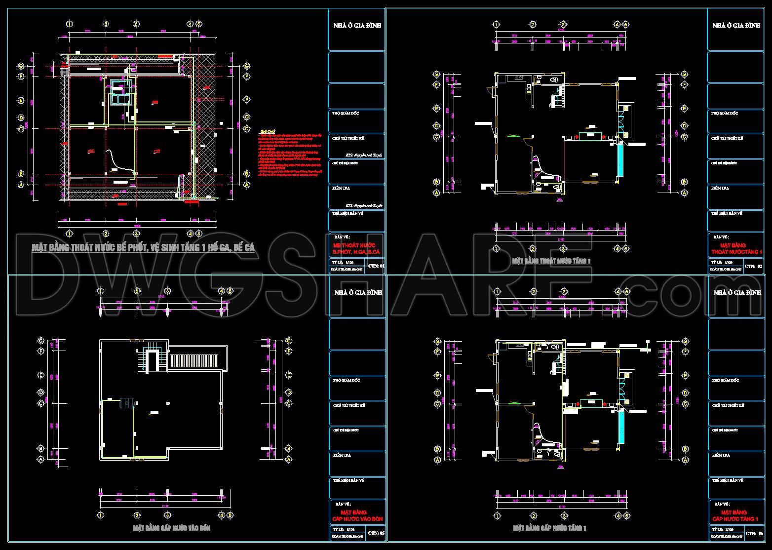
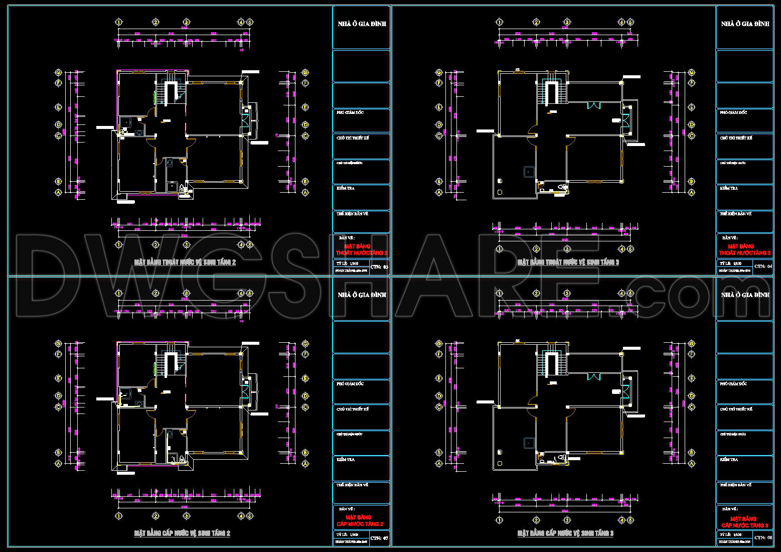
The set of 2-story house water supply and drainage CAD drawings provides a comprehensive overview of essential systems within a residential building. These CAD drawings are strategically divided into two main categories: water supply systems and drainage systems. As an architectural professional, assessing these technical drawings reveals the meticulous planning and detail that contribute to efficient and functional housing designs.
Focusing initially on the water supply system, the CAD drawings display crucial components like the functional floor plan layout for each floor, indicating where water lines are routed to various fixtures. This layout helps to identify the connection points to the main water supply, ensuring optimal water pressure and accessibility. The elevations and sections are included where necessary, providing a three-dimensional perspective that highlights vertical routing, particularly useful for multi-story arrangements. These are essential for architects and engineers to accurately coordinate the routing of pipes and prevent clashes with other systems.
The drainage CAD drawings similarly include a detailed floor plan that identifies the placement and direction of drainage pipes. Key elements like the construction detail drawings showcase the technical specifications of various drainage components, such as traps and slope requirements, ensuring proper flow and the prevention of backflow. Grid lines, dimensions, and level markers are meticulously included to provide precise location referencing, aiding construction teams during the installation phase.
The practical application for these CAD drawings is vast. Architects rely on them during the design development phase to confirm that the integration of water systems aligns with the broader architectural plans. Interior designers benefit from these drawings while preparing technical details for fixtures and fittings, ensuring that aesthetic decisions are grounded in practical feasibility. Construction teams use these documents extensively, providing a reference for installation and coordination across mechanical, electrical, and plumbing systems.
One of the standout benefits of these CAD drawings is their high technical accuracy, offering easy modifications and reuse in AutoCAD. This adaptability not only improves coordination between design and construction teams but also significantly reduces errors, leading to cost optimization during the building process.
These CAD DWG files are shared for free, offering a valuable resource for design reference, study and research, and as a base for technical drawing development. The ease of access to such detailed and accurate documentation makes them an essential tool for professionals and students alike, fostering better understanding and innovation in architectural and construction practices.
I also recommend downloading other Mechanical, Electrical CAD drawings for your project reference.
- File format: .DWG
- Size: 1 MB
- Source: DWGshare
- AutoCAD platform 2018 and later versions. For downloading files there is no need to go through the registration process
If you find our work useful, your support would mean a lot and help us grow even better.DONATE
Related posts
517. Water Supply and Drainage Plans for Residential Building DWG
131. Free download electrical and internet cad drawings for 3-storey house
335. Detailed Generator Room CAD Drawing (Floor Plan, Sections) Free Download
358. Free Lighting Layout CAD Drawing – Electrical Plan for Building (DWG Download)
345. Free Download CAD Electrical Wiring Diagram of 5-Storey Hotel
150. Free Download Electrical Design Drawings for a 2-Story Townhouse
310. CAD drawings detailing the design of water supply and drainage systems for a 3-story townhouse
67. Detailed CAD design drawings for the water supply system in a 3-story townhouse
152. Free Download of Electrical and Plumbing Design Drawings for a 4-Story Townhouse