

714. Reservoir Site Development Plan CAD Drawing DWG Download
Advertisements
714. Reservoir Site Development Plan CAD Drawing DWG Download
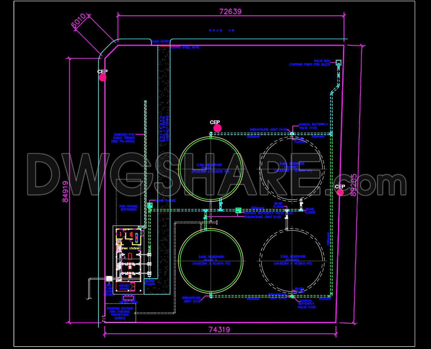
The Reservoir Site Development Plan presents an intricate CAD drawing designed specifically for the development of a reservoir site. This site plan is a crucial tool for architects and construction professionals, providing a comprehensive layout that coordinates various technical elements essential for effective project execution. Highlighted in this CAD drawing is the layout of the reservoir site, and it effectively demonstrates how each component fits into the overall plan.
Key components visible in this drawing include:
Detailed site layout
Reservoir tanks and their dimensions
Grid lines and precise dimensions
Placement of essential utility connections
Access roads and pathways
The presence of detailed site layout ensures that architects can accurately strategize the placement and design of the reservoir, considering factors like space utilization and structural integrity. Each reservoir tank, marked with specific dimensions, allows designers to understand the scale and requirements for each unit, facilitating better planning and allocation of resources.
Grid lines and precise dimensions form the backbone of the drawing, providing a spatial framework that guides construction teams in aligning their work with the initial design intent. These guide markings are indispensable for maintaining accuracy and alignment throughout the construction process.
The drawing’s inclusion of utility connections is particularly vital for ensuring that the site functions efficiently. This aspect enables a seamless coordination between different utilities, enhancing overall project feasibility and functionality. Moreover, the layout of access roads and pathways is essential for planning logistics and ensuring accessibility, both during construction and in the final operational phase.
The practical benefits of this CAD drawing are significant. Its high level of technical accuracy minimizes errors, allowing for smooth coordination between design, planning, and construction phases. The ability to modify and adapt this design within AutoCAD makes it highly versatile for future project phases or similar site developments, optimizing both cost and resources.
These CAD DWG files are shared freely, offering an invaluable reference for designers and students alike. They serve as a base for technical drawing development, research, and detailed design exploration, promoting enhanced learning and understanding in architectural design and civil engineering.
The Reservoir Site Development Plan thus stands out as a crucial resource, driving efficient planning and successful project realization through its detailed and meticulously crafted drawings.
I also recommend downloading other Mechanical, Electrical CAD drawings for your project reference.
- File format: .DWG
- Size: 1 MB
- Source: DWGshare
- AutoCAD platform 2018 and later versions. For downloading files there is no need to go through the registration process
Advertisements