
450. Download Reinforced Concrete Slab Reinforcement CAD Drawings with Rebar Details & Schedules (DWG)
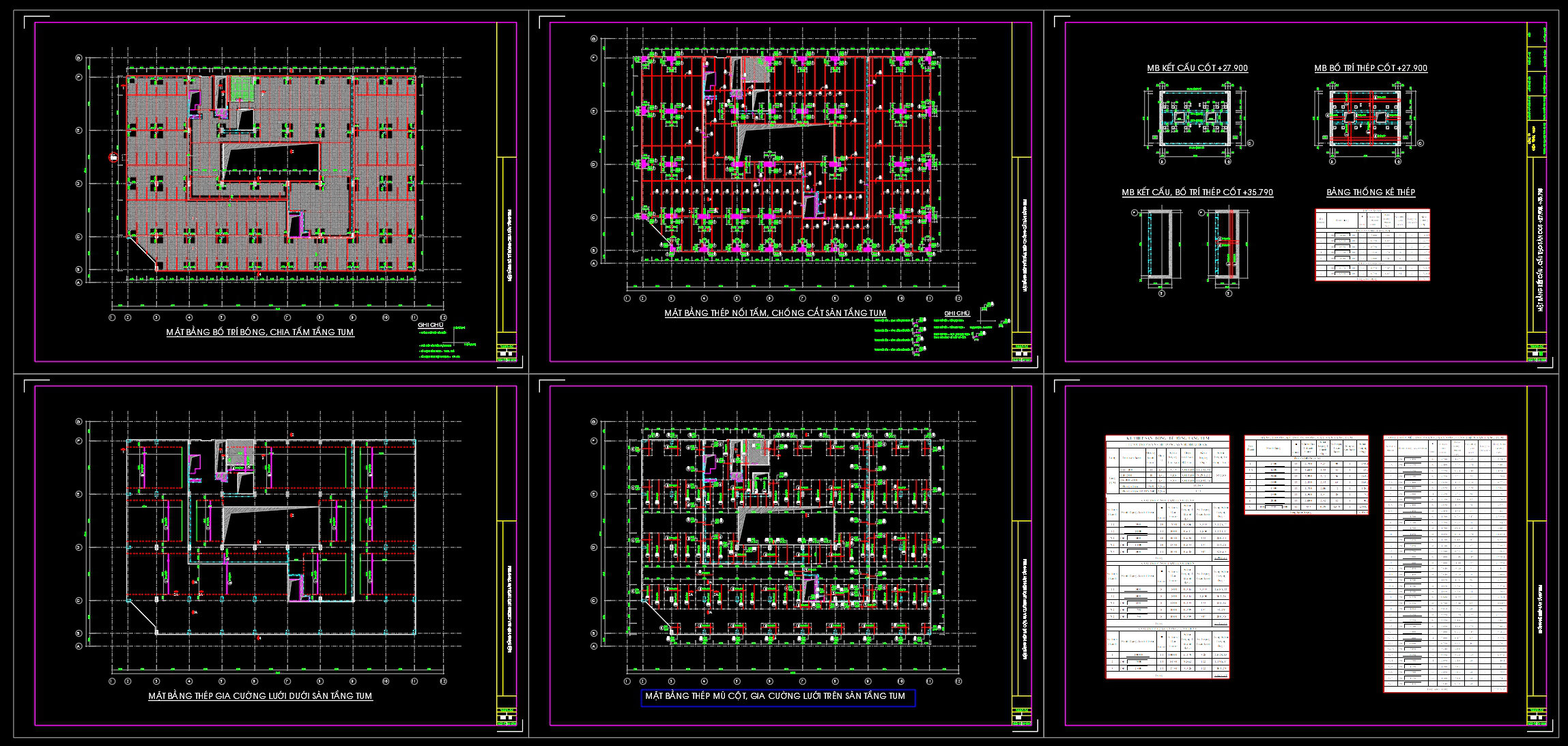
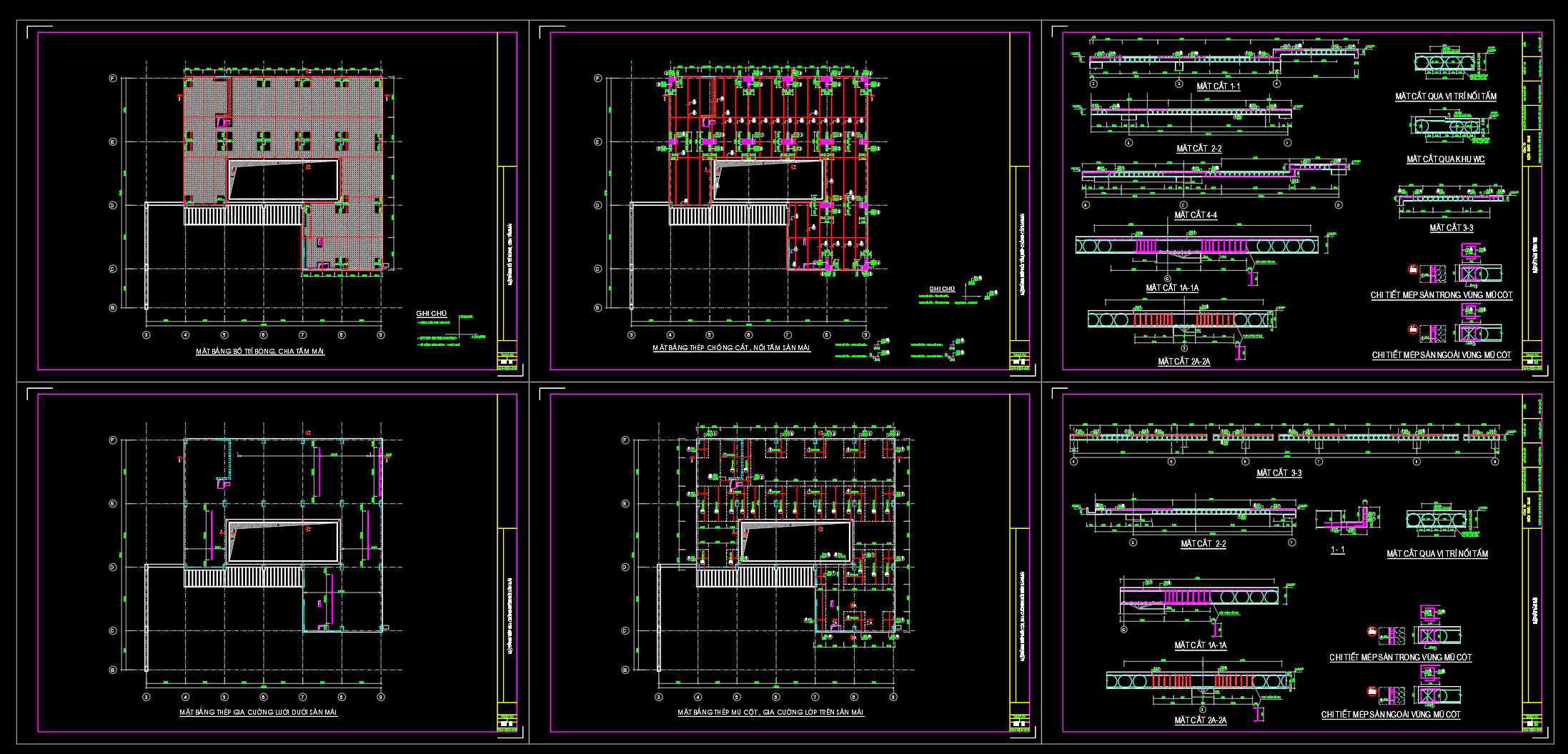
The CAD DWG drawings available for download here are essential resources for professionals dealing with reinforced concrete slab reinforcement. These structural drawings are meticulously detailed, providing an invaluable visual guide for reinforcements, including comprehensive rebar details and schedules. At the forefront, these technical drawings exhibit high precision, crucial for any architectural and construction practice.
Each drawing showcases a variety of components essential for both design and execution. Among the visible features are:
Functional floor plan layout: These plans outline the overall layout, helping architects visualize space distribution. They include grid lines, dimensions, and level markers, ensuring that every component fits perfectly within the spatial confines.
Reinforcement details and schedules: Detailed rebar layouts are depicted, providing specifics on placement, type, and gauge, vital for structural integrity. These schedules offer precise quantities and detailed specifications down to the smallest unit.
Sections and elevations: These drawing types reveal essential construction details, helping professionals understand the vertical elements and cross-sectional views of the slabs. They highlight the interaction of different structural components, crucial for realizing complex architectural designs.
The practical application of these drawings extends across various stages of project development. For architects, they function as an essential tool for design development, enabling a seamless transition from concept to reality. The availability of these detailed plans ensures that architects can refine and perfect designs with enhanced accuracy.
Interior designers also find great utility in these drawings when preparing technical details. The precision afforded by reinforced concrete slab reinforcement plans aids in the integration of interior features without compromising structural elements. By conforming to the exact specifications of the drawings, interior designers can ensure that the overall aesthetics and functionality are maintained.
For construction teams, these files serve as a reliable reference point, simplifying coordination during the building process. The high technical accuracy of the CAD files reduces errors significantly, facilitating smoother transitions from plans to construction. This leads to improved project timelines and optimized costs.
Moreover, these CAD DWG files are shared for free, making them an attractive option for those seeking design references, engaging in academic study, or developing a base for future technical drawings. The ease of modification and reuse within AutoCAD streamlines project adjustments and iterations.
By leveraging these expertly crafted drawings, professionals can enhance coordination between design and construction, ultimately delivering projects with higher efficiency and accuracy.
I also recommend downloading other Construction methods CAD drawings for your project reference.
- File format: .DWG
- Size: 5 MB
- Source: DWGshare
- AutoCAD platform 2018 and later versions. For downloading files there is no need to go through the registration process
If you find our work useful, your support would mean a lot and help us grow even better.DONATE
Related posts
356. Free Download of Structural CAD Drawings for 11.7m x 18.5m Reinforced Concrete Townhouse
238. Structural Drawings Of 4-Story House A Complete Project 4m x 14m For Download
353. Free Download of Structural CAD Drawings for 7m x 9m Reinforced Concrete Townhouse
687. Utility Manhole and Handhole CAD Details DWG – Free Download
256. Structural Drawings Of 3-Story House A Complete Project 3.7m x 15m For Download
602. Free Download CAD File – Atrium Roof Grid Structure Details
271. Structural Drawings Of 3-Story House A Complete Project 14.2m x 19.7m For Download
707. Raft Foundation Layout Design – Free AutoCAD Drawing Download
728. Side Wall Elevation and Bracing Details CAD Drawings DWG