
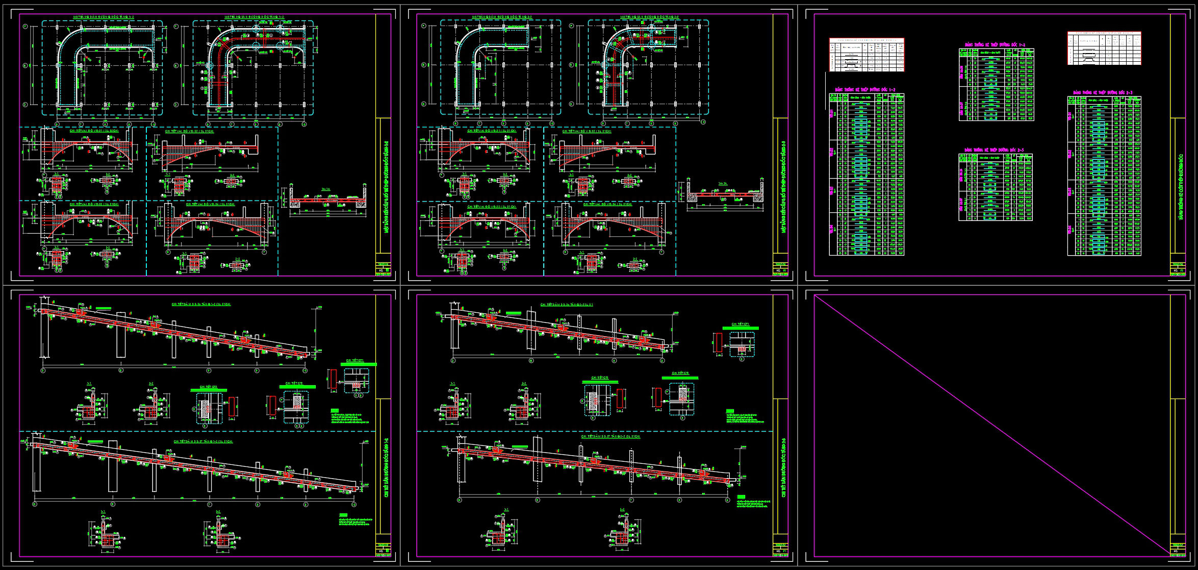
451. Download Reinforced Concrete Curved Beam CAD Drawings with Reinforcement Details & Bar Schedules
The reinforced concrete curved beam CAD drawings with detailed reinforcement specifications serve as invaluable resources for architects, engineers, and construction professionals. These structural drawings display a comprehensive set of information required for the meticulous design and precise construction of reinforced concrete beams with complex curvatures.
At the core, these drawings provide essential details that enhance the accuracy and efficiency of design documentation. The sheet includes key elements such as:
Reinforcement layout plans
Detailed sections showing beam configurations
Bar schedules with precise specifications
Grid lines and dimension markers for accurate placement
Level markers to ensure proper alignment in construction
Each component is crafted to facilitate seamless coordination between engineering design and construction implementation. The reinforcement layout plans depict the exact placement and configuration of steel bars within the concrete beams, ensuring structural integrity and compliance with design requirements. Detailed sections offer insights into the beam cross-sections, underscoring the importance of precise execution in the field.
The bar schedules provide exhaustive lists of reinforcement bars used, specifying sizes, quantities, and placements. This ensures all involved parties have access to consistent data, crucial for minimizing errors and optimizing costs during construction.
For architects, these CAD drawings are indispensable during the design development phase, enabling them to visualize structural components accurately. Interior designers can rely on the technical details provided to integrate structural elements into their layouts seamlessly. Meanwhile, construction teams benefit immensely as these drawings act as reference points for on-site coordination and execution.
One of the standout features of these CAD files is their adaptability for various projects. The high technical accuracy allows for easy modification and reuse in AutoCAD, making these drawings a practical tool for ongoing reference or as a foundation for developing future technical drawings.
Available for free download, these CAD DWG files can be utilized as a robust design reference, an educational resource for study and research, or a base for further technical drawing development. The precision and clarity embedded in these files contribute significantly to enhancing coordination between design and construction, thereby reducing errors and facilitating cost optimization across projects.
I also recommend downloading other Construction methods CAD drawings for your project reference.
- File format: .DWG
- Size: 2 MB
- Source: DWGshare
- AutoCAD platform 2018 and later versions. For downloading files there is no need to go through the registration process
If you find our work useful, your support would mean a lot and help us grow even better.DONATE
Related posts
43. Free Download CAD Construction Drawings of Cantilever Beam-Slab Method
338. Free Download of Structural CAD Drawings for 3.7m x 13.8m Reinforced Concrete Townhouse
363. Free Download of Structural CAD Drawings for 7.5m x 13.5m Reinforced Concrete Townhouse
322. Free Structural CAD Drawings Available for 7.4m x 17.2m Reinforced Concrete Townhouse
134. Cad Drawing Of Circular Column Scaffolding Details For Download
728. Side Wall Elevation and Bracing Details CAD Drawings DWG
146. Cad Drawing Of Staircase Reinforcement Concrete For Download
92.Autocad Drawing Of General Plan Of Reservoir Structure For Download
344. Free Download of Structural CAD Drawings for 5.7m x 8.5m Reinforced Concrete Townhouse