
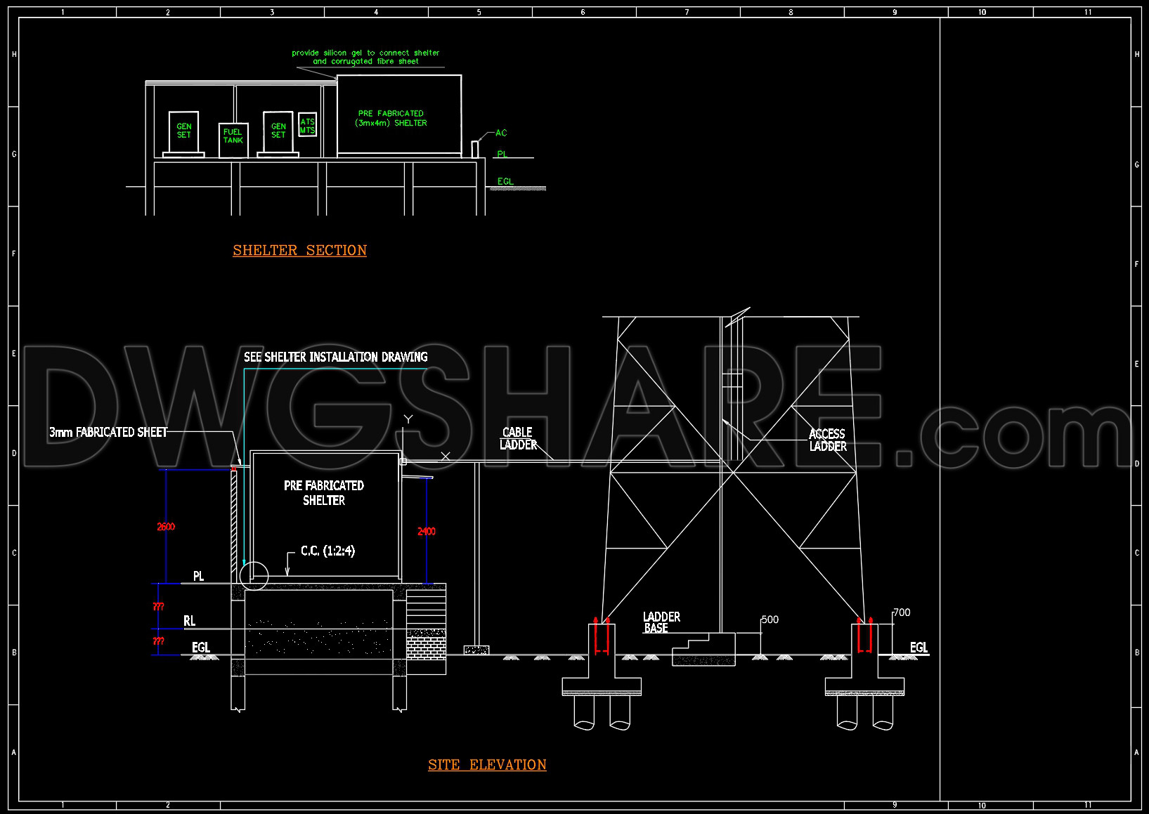
756. Telecom Tower Shelter Section & Site Elevation CAD Drawing DWG
The Telecom Tower Shelter Section and Site Elevation CAD Drawing DWG presents a detailed architectural depiction essential for the planning and construction of telecom infrastructures. This set of drawings includes both a shelter section and a site elevation, each serving distinct purposes in the overall design and execution of the project. These details are vital for both architects and construction teams, providing a clear blueprint for execution.
The shelter section drawing outlines the structural components and internal layout of the prefabricated shelter. It includes elements such as generator sets, fuel tanks, and ATS panels, meticulously arranged to ensure functionality and accessibility. The section illustrates the use of 3mm fabricated sheets to form the exterior, showing the technical integration of materials essential for the durability and protection of sensitive equipment. This internal perspective aids architects in understanding how space is utilized and optimized within the shelter, allowing for seamless coordination during the design development stage.
Moving to the site elevation, this drawing provides a comprehensive view of the telecom tower in relation to its surroundings. It highlights the cable and access ladders in place for maintenance and safety, detailed dimensions, and elevation markers that are crucial for on-site construction teams. The elevation view indicates the positioning of the tower structure, foundation specifics, and operational heights necessary for proper alignment and installation. This facilitates effective communication and coordination among construction teams, ensuring the project adheres to the intended design and planning standards.
The presence of grid lines, detailed dimensions, and level markers across these drawings demonstrates a high level of technical accuracy. This precision not only facilitates easy modification and reuse within AutoCAD but is invaluable for reducing errors and optimizing costs during construction phases. By offering these files for free, they become an excellent resource for professionals looking for design references, as well as for students or researchers examining technical drawing applications within telecom projects.
In essence, these CAD drawings provide a comprehensive resource that enhances collaboration between design and construction teams. Their technical soundness and ease of adaptability make them an indispensable tool in the efficient execution of telecom infrastructure projects.
I also recommend downloading other Cad Details CAD drawings for your project reference.
- File format: .DWG
- Size: 196 KB
- Source: DWGshare
- AutoCAD platform 2018 and later versions. For downloading files there is no need to go through the registration process
If you find our work useful, your support would mean a lot and help us grow even better.DONATE
Related posts
701. Free Download Precast Boundary Wall Elevation and Section Details CAD DWG
636. Download Free DWG AutoCAD Drawing of Bridge Vertical Profile and Sections
225. Structural Drawings Of 2-Story House A Complete Project For Download
176. CAD drawing Offices structures free download
202. CAD drawing Of Bunglaw Foundation template Free download
400. Free Download of Structural CAD Drawings for 10m x 17.5m Reinforced Concrete Townhouse
300. Structural Drawings Of 3-Story House A Complete Project 5.7m x 15.7m For Download
754. Swimming Pool Overflow Gutter Detail CAD Drawing DWG
81.Autocad Drawings Of Tower Crane Foundation Details For Download