
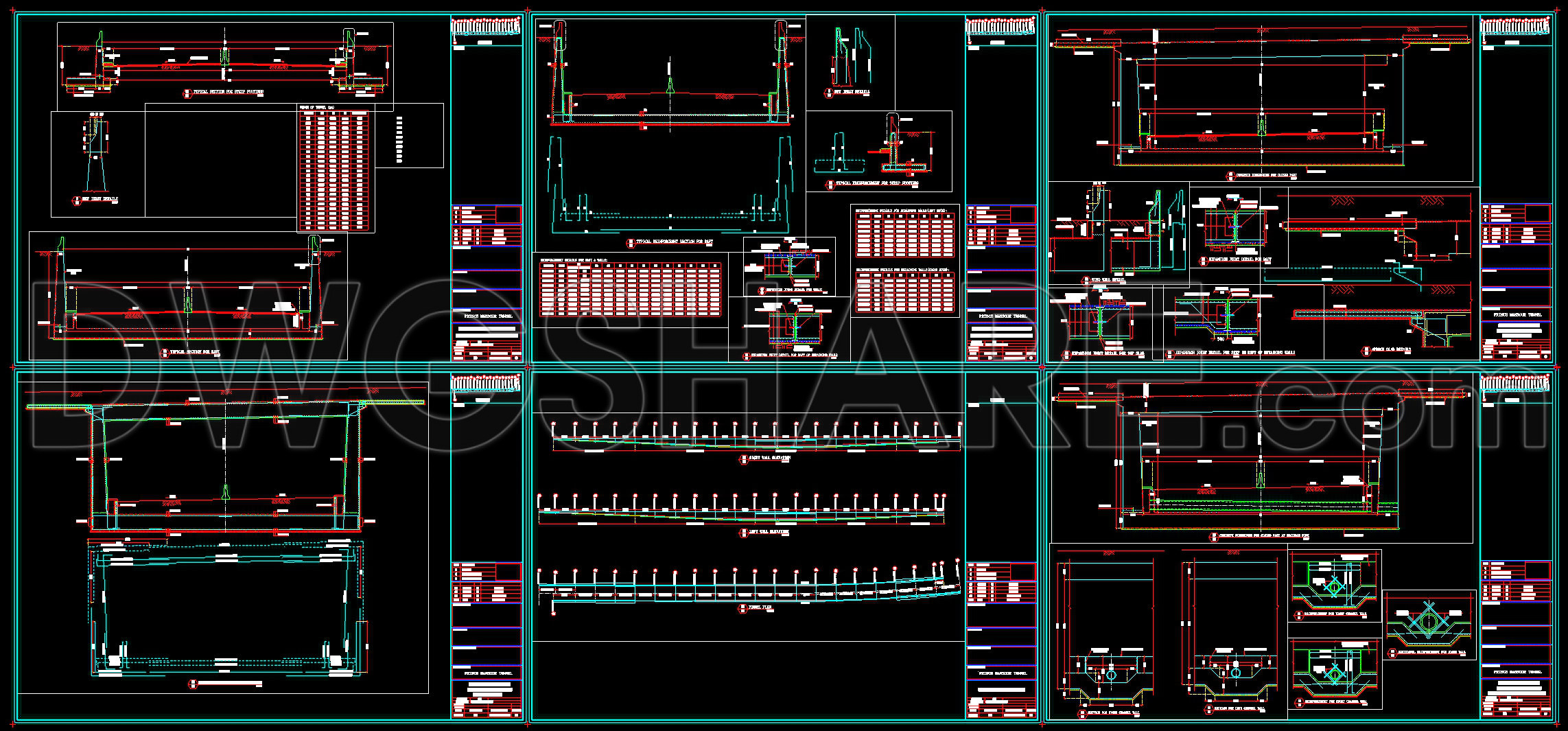
759. Detailed Tunnel CAD Drawings – Plan, Profile & Cross Sections
In the realm of modern tunnel construction, the significance of detailed CAD drawings cannot be overstated. These meticulously crafted plan, profile, and cross-section drawings are essential for ensuring precision and efficiency throughout the construction process. The featured drawings provide a comprehensive view, indispensable for architects, construction managers, and engineers aiming to execute a flawless project.
The first critical element is the plan view, which offers a top-down perspective of the tunnel layout. This view is crucial for understanding the overall alignment and spatial orientation of the project. Key features such as grid lines, dimensions, and level markers are clearly displayed, ensuring that every element aligns perfectly with regulatory and design standards. These plans serve as the foundation upon which the entire construction steps are based, providing a roadmap for both design and implementation phases.
Complementing the plan view are the profile drawings. These depict a side view of the tunnel, illustrating the progression of the project from start to finish. The profile view is vital for grasping how different sections of the tunnel interact with the terrain. It highlights elements such as elevation changes, which are pivotal for understanding how the tunnel navigates through varying earth materials.
Next, the cross-section drawings delve deeper into the interior structure of the tunnel. These sections reveal the detailed composition, including wall structures and support mechanisms. Understanding these sections is essential for ensuring structural integrity and operational safety. The cross sections offer insights into the tunnel’s capacity to withstand environmental pressures, illustrating how components like reinforcements and bracing are strategically employed.
Each drawing type plays a unique role within design documentation and on-site construction processes. Architects use these drawings during design development, ensuring their concepts are structurally feasible. Interior designers rely on the detailed sections for preparing technical details, ensuring aesthetic elements do not compromise structural soundness. For construction teams, these drawings are a constant reference point, aiding in accurate implementation and boosting coordination across various teams.
The practical value of these CAD drawings is immense. Offering high technical accuracy, they are easily modifiable and reusable within AutoCAD, which streamlines updates to designs and fosters efficient design-build iterations. By facilitating improved coordination between design and construction teams, these drawings minimize errors and optimize costs, proving indispensable in high-stakes construction projects.
For professionals seeking reliable resources, these CAD DWG files are accessible for free, suitable for design reference, study, or as a base for further technical development.
I also recommend downloading other Mechanical, Electrical CAD drawings for your project reference.
- File format: .DWG
- Size: 3 MB
- Source: DWGshare
- AutoCAD platform 2018 and later versions. For downloading files there is no need to go through the registration process
If you find our work useful, your support would mean a lot and help us grow even better.DONATE
Related posts
451. Free CAD drawings – Emergency staircases for 18‑story building
170. Complete steel structure drawing 2 story
82. CAD drawings detailing the design of water supply and drainage systems for a 6-story townhouse
751. Roof Slab Support Details – Free AutoCAD DWG Drawing
507. Free Download High-Rise Apartment Fire Protection CAD Drawings
93. CAD drawings detailing the design of water supply and drainage systems for a 3-story townhouse
223. Complete Air Conditioning HVAC CAD Drawings for a Multi-Story Building
266. House Plumbing System CAD Drawings – Water Supply, Drainage and Septic Tank
432. Free High-Rise Staircase & Elevator CAD Drawings – Full Structural Details & Sections