
786. Residential House Architectural CAD Drawings – Floor Plans, Elevations & Sections
In the realm of architectural design, the Residential House Architectural CAD Drawings are invaluable tools that offer intricate insights into the layout and construction of a dwelling. These comprehensive CAD files include detailed floor plans, elevations, and sections, each serving a crucial purpose in the design and construction process.
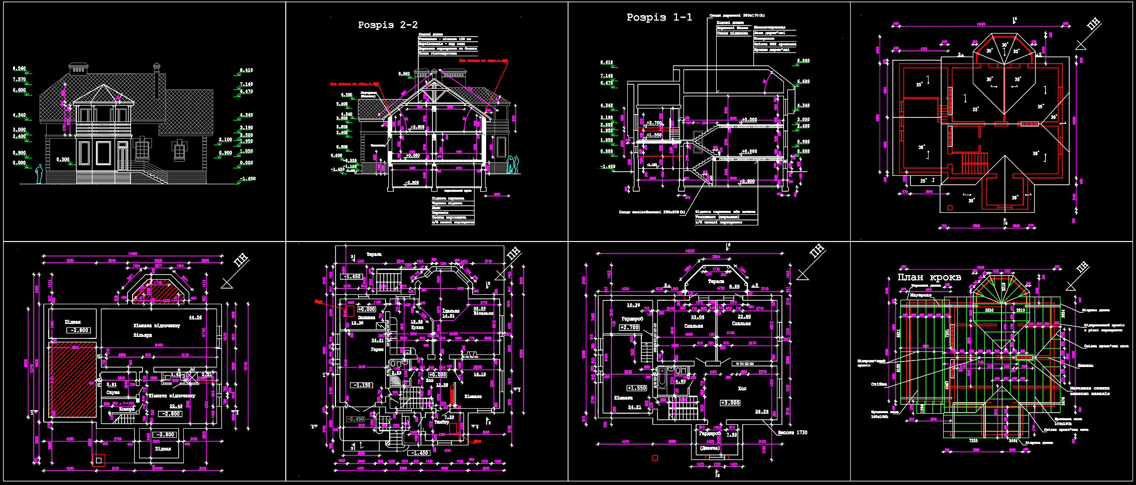
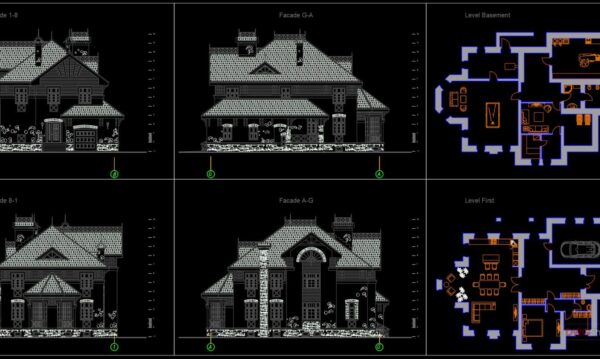
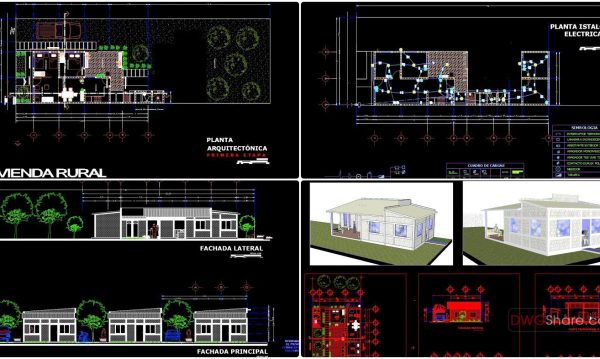
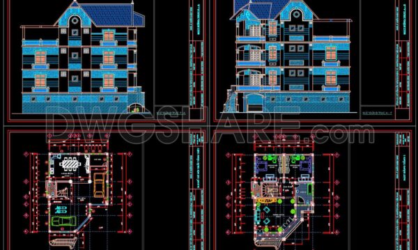
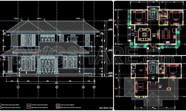
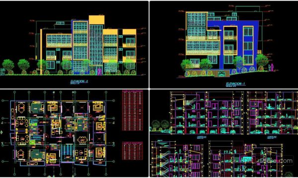
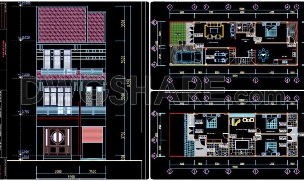
The floor plans provide a bird’s-eye view of the house’s internal layout. They meticulously depict the arrangement of rooms and spaces, highlighting critical elements such as doors, windows, and staircases. These plans are essential during the design development phase, allowing architects to optimize space utilization while maintaining aesthetic balance. The floor plans feature precise grid lines, dimensions, and level markers, ensuring that all spatial relationships are accurately represented. Such details are crucial for interior designers when selecting finishes and fittings, ensuring that every component aligns perfectly within the given space.
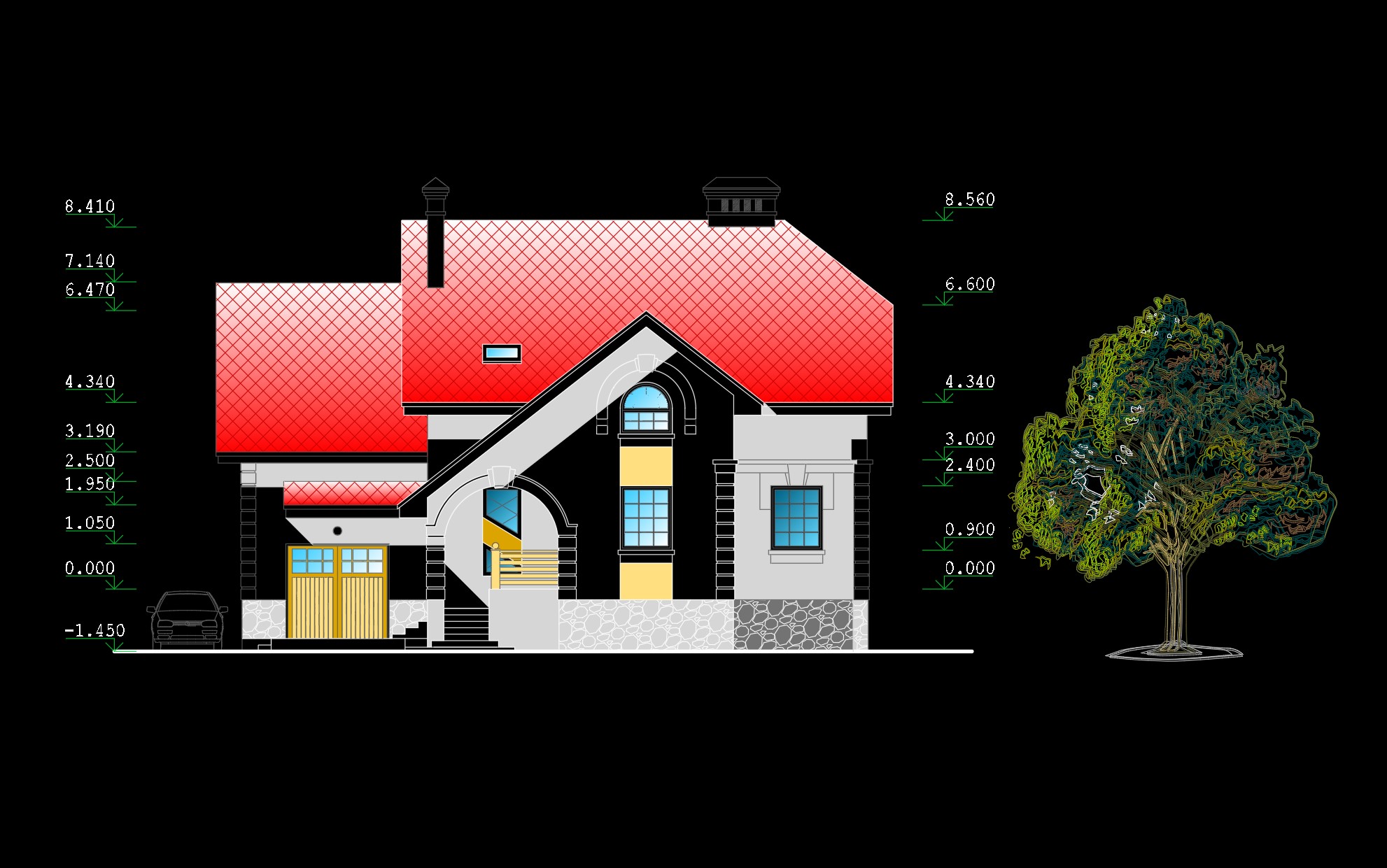
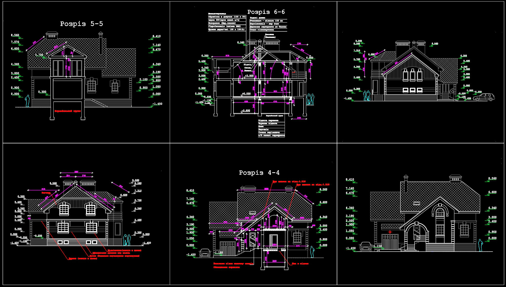
Moving to the elevations, these drawings present the exterior facades of the house. They showcase the architectural styling and materials used, offering a visual guide to the building’s appearance upon completion. Elevations are indispensable for both architects and clients, providing a clear understanding of how the structure will integrate into its surrounding environment. They also play a vital role in obtaining building permits, as they illustrate compliance with zoning laws and aesthetic guidelines.
Sections cut through the building to reveal internal structural elements. By viewing these vertical slices, construction teams can discern the composition of walls, floors, and roofs. This information is pivotal for engineers and builders alike, providing the necessary data to ensure structural integrity and facilitating the coordination of plumbing, electrical, and HVAC systems.
The high technical accuracy of these CAD drawings ensures that modifications and updates are straightforward in AutoCAD, allowing architects to quickly adapt designs in response to client feedback or regulatory requirements. This flexibility enhances communication between design and construction teams, reducing errors and optimizing costs.
These CAD DWG files are available free of charge, making them an ideal resource for students, researchers, and professionals. They serve as a foundational reference for developing further technical drawings or as a study tool for understanding residential architectural design.
I also recommend downloading other Cad Details CAD drawings for your project reference.
- File format: .DWG
- Size: 2 MB
- Source: DWGshare
- AutoCAD platform 2018 and later versions. For downloading files there is no need to go through the registration process
If you find our work useful, your support would mean a lot and help us grow even better.DONATE
excelente poder tener a mano esta maravilla, mil gracias
Thank you! We’re delighted to welcome you to the AutoCAD DWGshare community.