
195. Complete Residential Water Supply and Drainage System CAD Drawings DWG
In the realm of architectural and construction design, the Complete Residential Water Supply and Drainage System CAD Drawings offer a comprehensive and detailed look into the planning and execution of essential building services for residential projects. These CAD drawings provide a meticulous breakdown of the water supply and drainage systems, crucial for ensuring functionality and compliance with relevant standards.
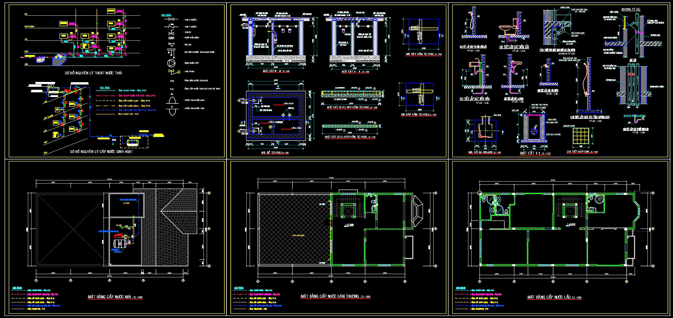
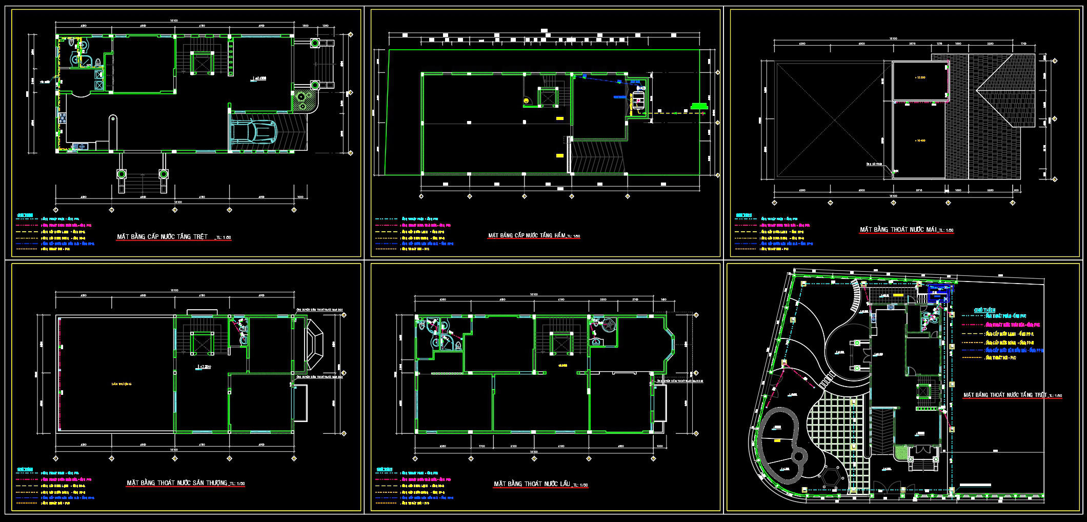
The primary drawing type presented is architectural plumbing plans, which are indispensable in both design development and construction oversight. Key elements visible in these drawings include:
Functional floor plan layout: Depicts the arrangement of rooms and plumbing features, ensuring all water supply points and drains align with architectural spaces.
Drainage and plumbing sections: These sections illustrate the vertical relationships and integration of systems through the building’s height, emphasizing how systems transition between floors.
Detailed plumbing schematics: Highlight the technical configurations of piping networks, fixtures, valves, and connection points, enhancing understanding for various stakeholders.
Grid lines, dimensions, and level markers: Precise measurements and reference points ensure accuracy in installation and facilitate cross-discipline coordination.
These CAD drawings serve multiple practical functions:
For architects, they provide a detailed blueprint of the water supply and drainage infrastructures, crucial for incorporating technical specifics into broader design strategies. Interior designers utilize these drawings when planning technical details around plumbing integration without compromising aesthetic values. Construction teams rely heavily on these drawings to align on-site execution with designed intents, ensuring water systems are installed correctly, safely, and efficiently.
The complete residential drainage system drawings enhance project delivery through key benefits such as high technical accuracy, enabling correct interpretations and implementations. Moreover, they allow for easy modifications within AutoCAD, accommodating changes throughout the project lifecycle. Their availability as a free resource makes them particularly valuable for design reference, educational purposes, and as a foundational base for further detail development. Ultimately, these CAD resources significantly improve coordination among design and construction teams, optimizing costs, and minimizing errors.
The value in these drawings remains apparent not only in the preliminary design phases but throughout construction, where clear, accurate visual documentation is paramount. By making these files openly accessible for educational and project development purposes, they serve the broader professional community, advancing knowledge and skill in effective system design and integration within residential structures.
I also recommend downloading other Mechanical, Electrical CAD drawings for your project reference.
- File format: .DWG
- Size: 1 MB
- Source: DWGshare
- AutoCAD platform 2018 and later versions. For downloading files there is no need to go through the registration process
If you find our work useful, your support would mean a lot and help us grow even better.DONATE
Related posts
348. Complete Plumbing Construction Drawings for Commercial Building
66. CAD drawings for detailed electrical designs for a 3-story townhouse
141. CAD drawings detailing the design of water supply and drainage systems for a 3-story townhouse
47. CAD drawings for detailed electrical designs for a 4-story townhouse
210. Residential Reflected Ceiling Plan & Lighting Layout CAD Drawings (DWG)
147. Free Download of Mechanical and Electrical Construction Design Drawings for a 4-Story House
57. CAD drawings for detailed electrical designs for a 3-story townhouse
20.Site Office and Administration Lighting and Power CAD
151. CAD drawings detailing the design of water supply and drainage systems for a 2-story townhouse