
368. Classical Villa Elevation CAD Drawing – Lightning Protection System Design
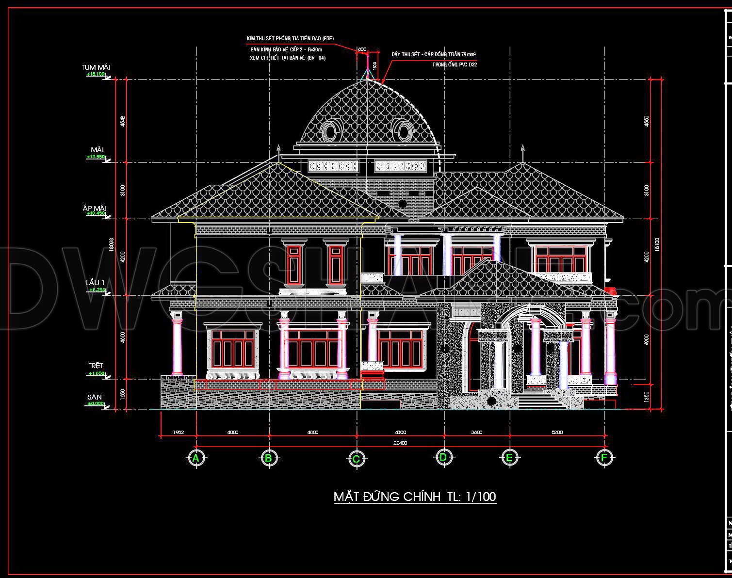
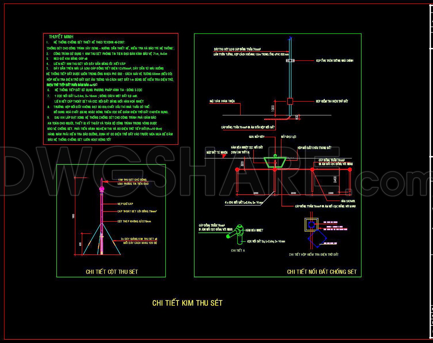
The Classical Villa Elevation CAD Drawing featuring a comprehensive Lightning Protection System Design provides a crucial insight into architectural and structural planning through detailed visual documentation. These drawings include both elevations and detailed construction layouts, essential for the effective design of classical architecture.
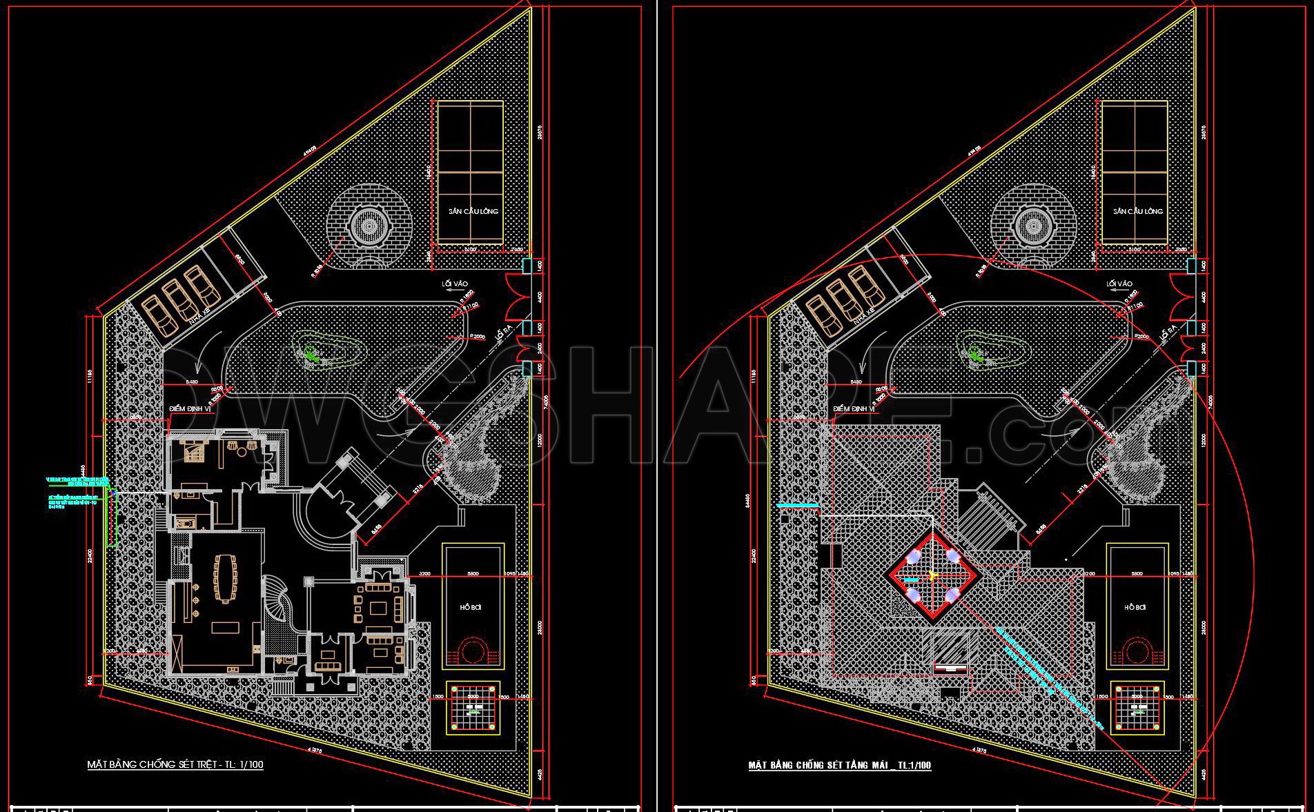
The primary file reveals a strategic integration of the lightning protection system within the villa’s architecture. Elevations illustrate the proportion and aesthetic alignment with existing classical villa elements, ensuring seamless design integration. The CAD file offers a clear representation of the structure’s perimeter and the placement of vertical and horizontal rods essential for lightning protection. By detailing the systems within the main structure and extending to peripheral areas like pools and outdoor courts, the drawings ensure holistic coverage.
Included with the elevations are detailed components such as grid lines, dimensions, and level markers. These features not only highlight spatial relationships but also guide the accurate installation of protective elements. The grid lines serve as a blueprint framework ensuring all installations adhere to site specifications, while dimension markers clarify the required distances between conductive elements, contributing to the structural safety and efficacy.
Further enhancing the value of this CAD drawing is the provision of detailed construction drawings focusing specifically on the technical aspects of the lightning protection system. Diagrams highlight connection points, grounding systems, and interface details with structural elements. This includes layouts for the essential metal conductors and grounding rods, displayed in scaled detail, promoting rigorous installation practice.
For architects, these drawings contribute significantly to the design development phase, allowing for the seamless incorporation of safety designs without compromising aesthetic or functional integrity. Interior designers leverage these details when planning space transformations to accommodate technical installations invisibly within interior layouts.
Construction teams benefit from the precision and clarity of these CAD files, which facilitate error reduction and optimize installation processes. The high technical accuracy of these drawings ensures adherence to safety standards and promotes cost management by minimizing potential reworks.
Available as a free resource, these files are indispensable for professional design reference, technical studies, and as foundational templates for future projects. The adaptability and ease of modification provided by AutoCAD make these drawings particularly valuable for iterative design processes, cementing their role in bridging design and construction.
I also recommend downloading other Cad Details CAD drawings for your project reference.
- File format: .DWG
- Size: 6 MB
- Source: DWGshare
- AutoCAD platform 2018 and later versions. For downloading files there is no need to go through the registration process
If you find our work useful, your support would mean a lot and help us grow even better.DONATE
Related posts
147. Free Download of Mechanical and Electrical Construction Design Drawings for a 4-Story House
215. Water Supply System Design CAD Drawings for Villa (DWG)
310. CAD drawings detailing the design of water supply and drainage systems for a 3-story townhouse
96. CAD drawings detailing the design of water supply and drainage systems for a 4-story townhouse
144. Free Download Electrical Design Drawings for a 3-Story Townhouse
278. Residential Water Supply & Drainage Plans – Plumbing System DWG
244. 2-Story House Water Supply & Drainage CAD Drawings
104. CAD drawings for detailed electrical designs for a 6-story townhouse
199. Complete Residential Water Supply and Drainage System CAD Drawings DWG