
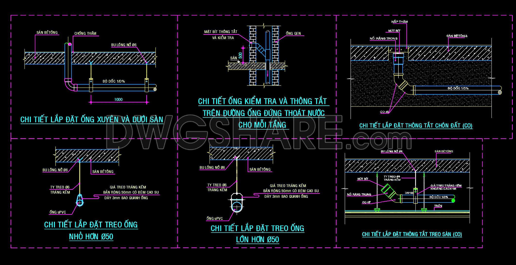
347. uPVC Drainage Pipe Support, Cleanout and Floor Penetration Details DWG
The provided CAD DWG drawing focuses on uPVC drainage pipe support, cleanout, and floor penetration details. These detail drawings are crucial in architectural and engineering documentation, providing clear guidelines for installation and ensuring the efficient functioning of the drainage systems.
The CAD file includes several essential components necessary for the installation of uPVC drainage systems. It is comprised of various detail drawings that illustrate installation techniques and best practices. Key elements visible in this detailed drawing set include:
Floor penetration details
Pipe cleanout configurations
Support systems for horizontal and vertical runs
Installation configurations for beneath-floor setups
Depicted gradient slopes for drainage efficiency
Each of these components is meticulously detailed for practical application. For example, floor penetration details show how pipes pass through structural flooring with waterproof sealing, ensuring no leakage occurs at intersections. Pipe cleanout configurations delineate access points, facilitating maintenance tasks, which are vital for ongoing system performance and longevity.
Moreover, the support systems for horizontal and vertical pipe runs are carefully laid out to ensure structural integrity and ease of access, which is paramount for both installation and future repairs. These support details provide crucial information on attachment methods and load-bearing considerations, ensuring the setup adheres to best practices.
Installation configurations beneath the floor are specifically addressed, showcasing methods to secure pipes while maintaining required gradient slopes. The depicted gradient in these drawings adheres to a precise 1% slope, optimizing fluid velocity and minimizing blockage risks by ensuring continuous flow.
These CAD drawings serve multiple purposes. Architects and engineers utilize them during design development to create integrated systems within building plans. Their detail-oriented nature makes them ideal for interior designers when coordinating with other building systems. For construction teams, these drawings offer a critical reference for accurate implementation and coordination, significantly reducing errors and enhancing project efficiency.
The high technical accuracy of these drawings allows for easy modification and reuse in AutoCAD, offering flexibility for future adjustments or adaptations. Shared for free, these CAD DWG files are perfect for design reference, study, and use as a base for further technical drawing development. Utilizing these resources can significantly aid in cost optimization and error reduction during the construction process.
I also recommend downloading other Mechanical, Electrical CAD drawings for your project reference.
- File format: .DWG
- Size: 133 KB
- Source: DWGshare
- AutoCAD platform 2018 and later versions. For downloading files there is no need to go through the registration process
If you find our work useful, your support would mean a lot and help us grow even better.DONATE
Related posts
244. 2-Story House Water Supply & Drainage CAD Drawings
338. Free Download of Mechanical and Electrical Construction Design Drawings for a 2-Story House
180. Plumbing CAD Drawings DWG – Water Supply & Drainage System
166. Complete Residential Electrical, Lighting and Communication System CAD Drawings DWG
181. Download Residential ELV Systems CAD Drawings – TV, Telephone & Network Layouts
251. Residential Electrical Layout CAD Drawings – 2 Floors
7.Electrical Lighting Cad Blocks free download
79. CAD drawings for detailed electrical designs for a 3-story townhouse
212. Residential Reflected Ceiling Plan & Lighting Layout CAD Drawings (DWG)