
648. 3-Storey Modern Villa CAD Drawing DWG – 24m × 12m, Floor Plans, Roof Plan and Architectural Elevations
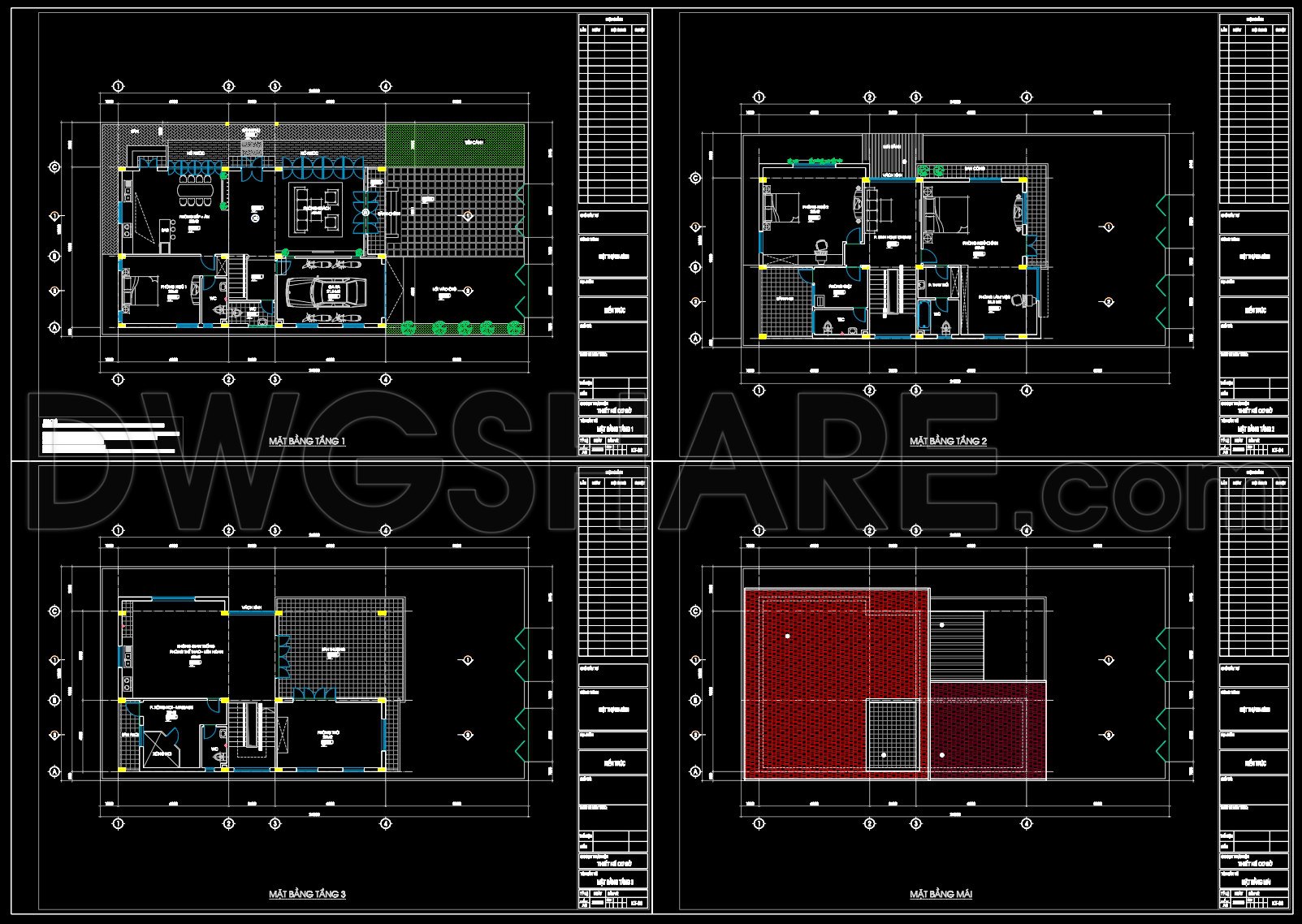
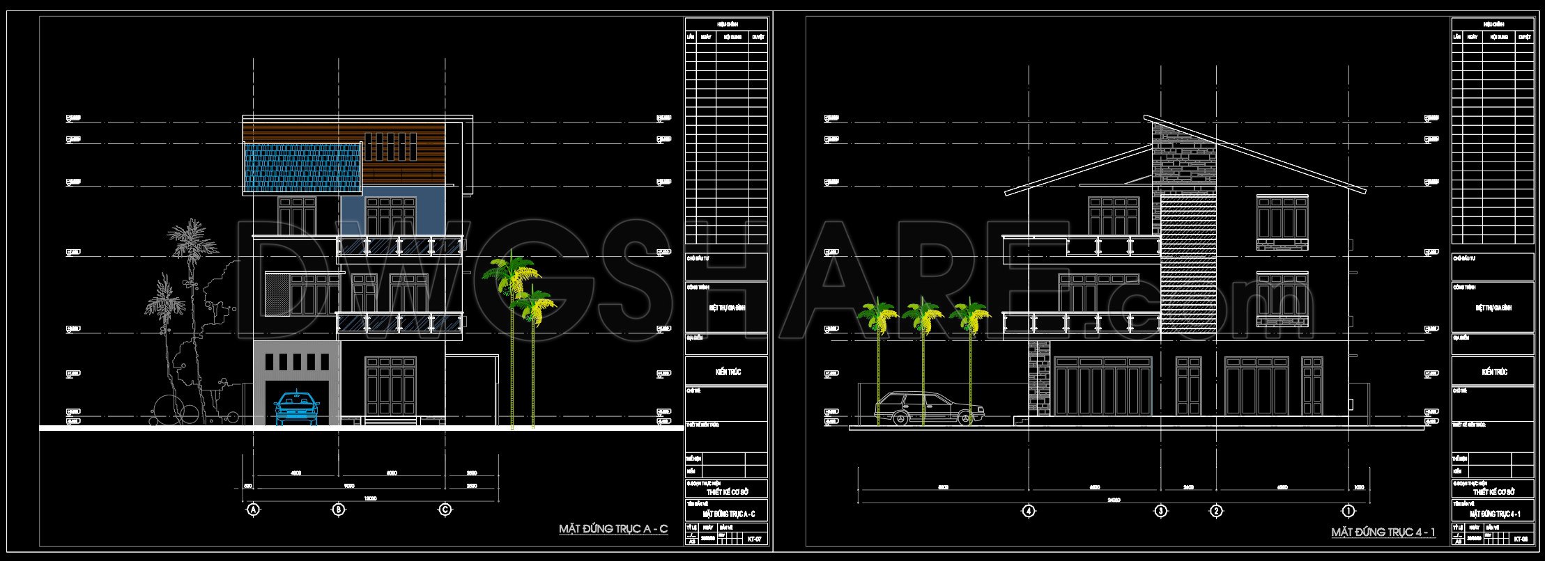
The 3-Storey Modern Villa CAD Drawing offers a comprehensive collection of floor plans, roof plans, and architectural elevations for a villa measuring 24 meters by 12 meters. These detailed architectural floor plans serve as critical resources for architects, interior designers, and construction teams, enabling seamless design development and construction coordination.
The functional floor plan layout delineates each floor’s organization, showcasing key areas such as living spaces, guest areas, and service zones. By illustrating the spatial arrangement and functional flow, these plans provide architects with a pristine framework to refine design ideas and communicate them effectively to clients.
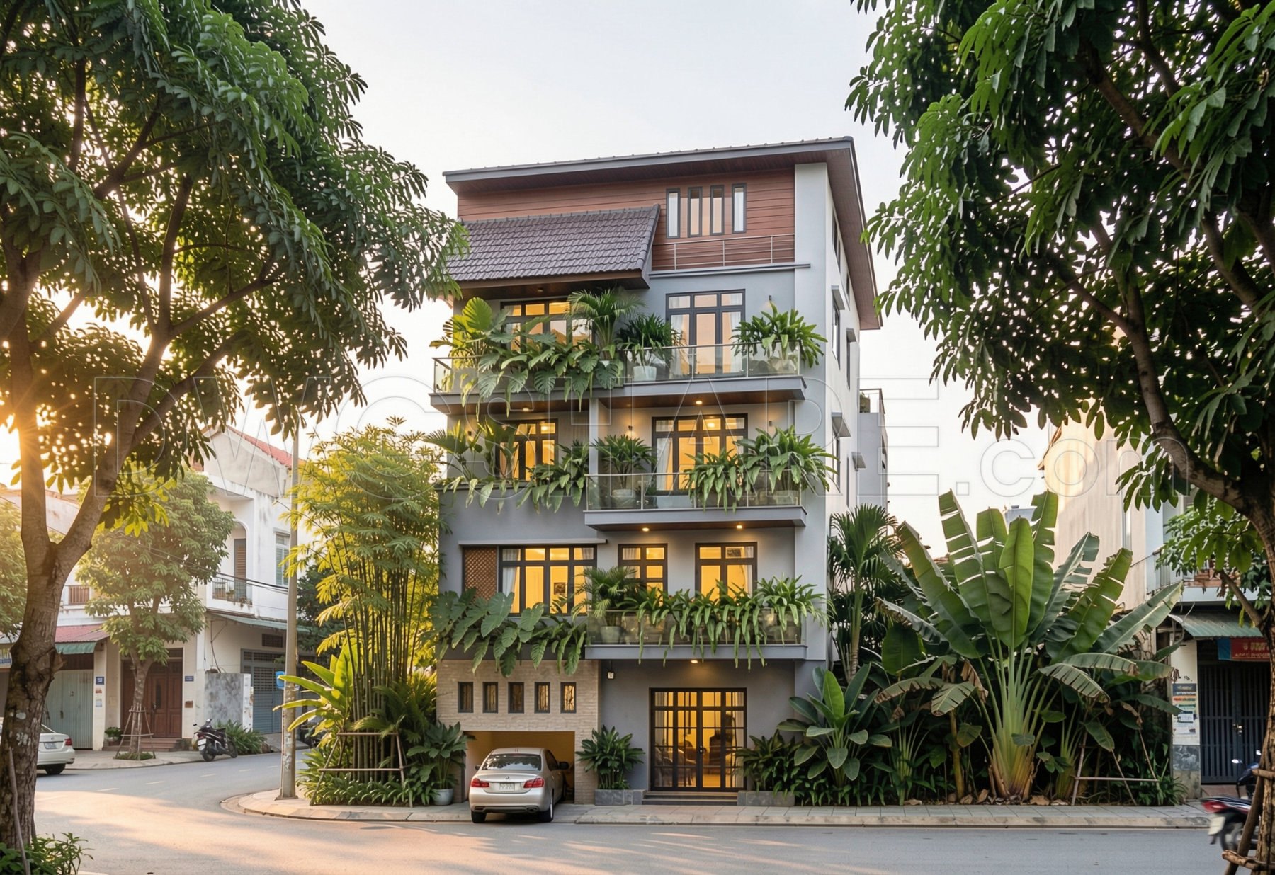
Elevations and sections within the drawings reveal the external facade and cross-sectional views, highlighting both aesthetic and structural elements of the modern villa. Architects rely on these drawings to ensure design consistency while contractors use them as a blueprint for accurate on-site construction, paying close attention to architectural details such as window placements and facade treatments.
Incorporated within these CAD files are precise grid lines, dimensions, and level markers, critical for maintaining accuracy in construction documentation. This meticulous attention to detail assists construction teams by offering a reliable point of reference during the build phase, ensuring that each structural component aligns perfectly as intended.
The drawings’ value resonates with interior designers who harness construction detail drawings to develop technical specifications for interior layouts, assist in furniture selection, and refine the overall aesthetic coherence of each room. These drawings minimize discrepancies and enhance communication between various design and construction stakeholders.
Available for free, the high technical accuracy and adaptability of these drawings in AutoCAD encourage their use as valuable resources for design reference, study, and research. Not only do they offer a foundational base for developing detailed technical drawings, but their well-coordinated structure also reduces potential on-site errors and aids in cost optimization by preventing material wastage and improving construction timelines.
I also recommend downloading other Houses CAD drawings for your project reference.
- File format: .DWG
- Size: 426 KB
- Source: DWGshare
- AutoCAD platform 2018 and later versions. For downloading files there is no need to go through the registration process
If you find our work useful, your support would mean a lot and help us grow even better.DONATE
Related posts
512. Free Download of Mechanical and Electrical Construction Design Drawings for a 2-Story House
524. 3-Story House Concept Design – Floor Plans, Elevations, Sections & Roof Plan CAD DWG
298. CAD design drawings for a 8-story townhouse with dimensions of 7m x 19.2m
Drawings Of 4-Story House A Complete Project 11.6m x 28.2m For Download
House at home, 180sqm, 5 bedrooms Full File Free Download
836. Residential Villa 2 Floors CAD Drawings – Plan, Elevation, Section
367. Download CAD Design Drawings for a 7-Story House with Dimensions 3.5m x 7.8m
618. 3-Story House 10 × 13.5 m – Floor Plans & Roof Plan CAD Drawing
278. CAD design drawings for a 4-story townhouse with dimensions of 4m x 10m