
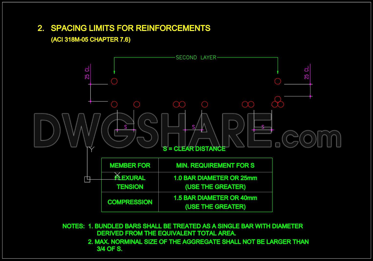
731. ACI 318M Reinforcement Spacing Limits CAD Drawings DWG
The ACI 318M Reinforcement Spacing Limits CAD Drawings are instrumental in the field of structural design, providing critical specifications for reinforcement bar spacing as outlined by the American Concrete Institute standards. As shown in the detailed drawings attached, these documents specifically address the spacing constraints that are crucial for ensuring the integrity and safety of concrete structures. The drawings are presented in DWG format, ideal for use in AutoCAD, which allows professionals in architecture and construction to efficiently reference, modify, and integrate these standards into broader design projects.
The primary focus of these drawings is on the structural drawings detailing the reinforcement bar placement, where spacing and alignment play a crucial role in the performance of structural elements. Notably, the drawings include:
Reinforcement bar layouts
Specification tables for bar diameter and clear spacing
Dimensional guidelines aligning with ACI 318M standards
Each drawing is precisely annotated to include mandatory clear distances for both flexural tension and compression members, ensuring adherence to structural safety norms. This detailed documentation aids architects during the design development phase, providing them with the flexibility to create robust structures that comply with industry standards. For interior designers, these technical details are indispensable when planning the integration of structural elements within interior layouts.
Construction teams rely heavily on these drawings for on-site implementation, ensuring that reinforcement bars are laid correctly to avoid errors that could lead to structural failures. The precision and clarity of these CAD files enhance coordination between design and construction teams, minimizing errors and optimizing costs.
An important aspect of these ACI 318M reinforcement spacing drawings is their high technical accuracy complemented by the ease of modification. This not only benefits active projects by streamlining the construction process but also provides an invaluable reference point for study and research purposes. Being shared for free, they serve as an excellent resource for anyone aiming to develop technical drawing skills or enhance their understanding of structural design practices.
By facilitating improved coordination and reducing potential errors, these CAD drawings prove invaluable both as a reference and as a base for further technical drawing development.
I also recommend downloading other Structural Details drawings for your project reference.
- File format: .DWG
- Size: 36 KB
- Source: DWGshare
- AutoCAD platform 2018 and later versions. For downloading files there is no need to go through the registration process
If you find our work useful, your support would mean a lot and help us grow even better.DONATE
Related posts
260. Structural Drawings Of 3-Story House A Complete Project 4.8m x 16.1m For Download
325. Free Download of Structural CAD Drawings for 5m x 14.8m Reinforced Concrete Townhouse
164. Structural Drawings Of Steel Roof Truss For Download
256. Structural Drawings Of 3-Story House A Complete Project 3.7m x 15m For Download
404. Free Download of Structural CAD Drawings for 7.2m x 12.6m Reinforced Concrete Townhouse
177. CAD drawing Bridge superstructure and foundations details free download
35.Steel Factory Ground Plan CAD
30.Steel Breeding Ground 3D Model CAD
9.Wooden Staircase Structure Details CAD