
226. Pump House & Water Tower – Complete CAD Drawings
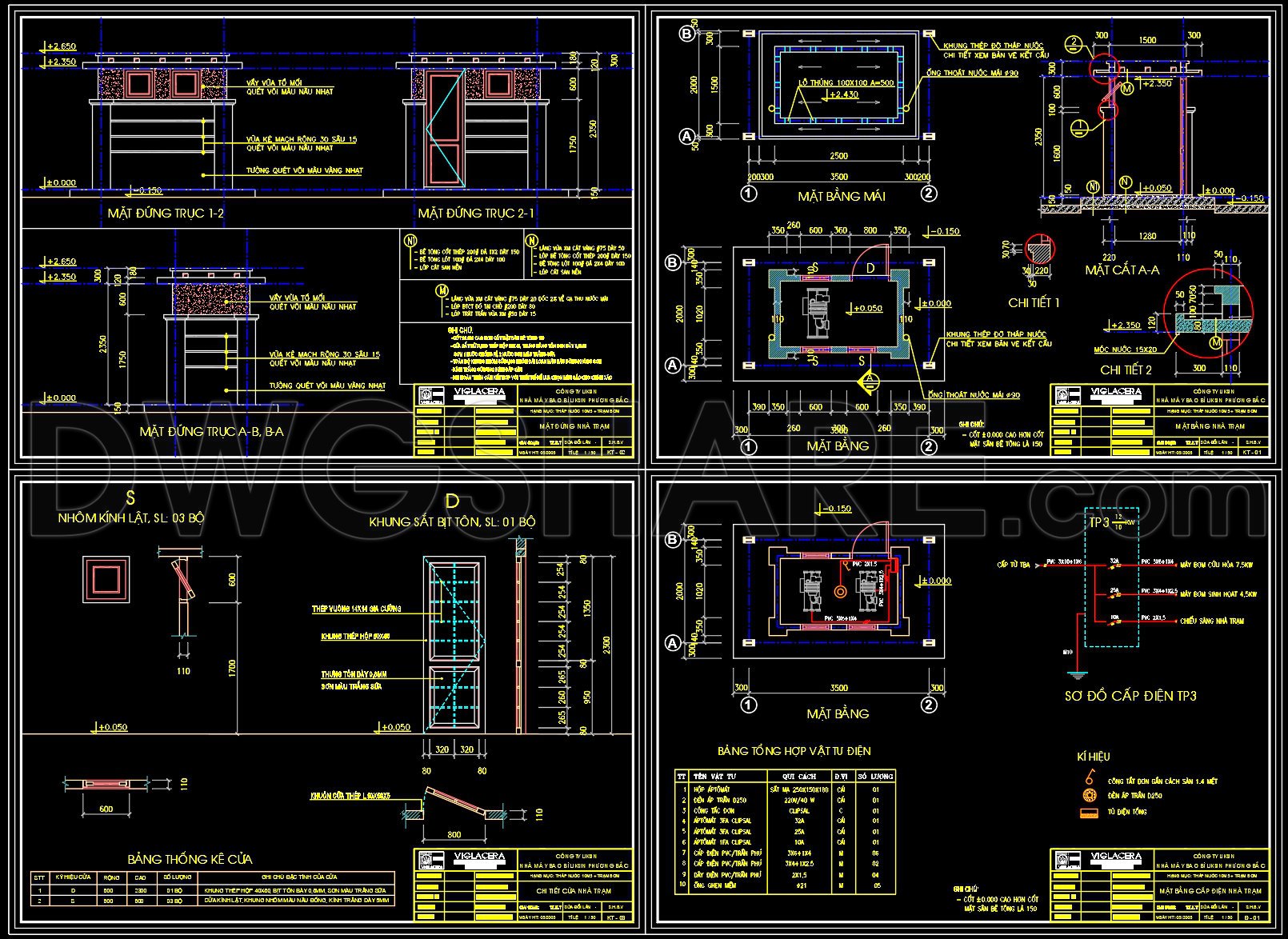
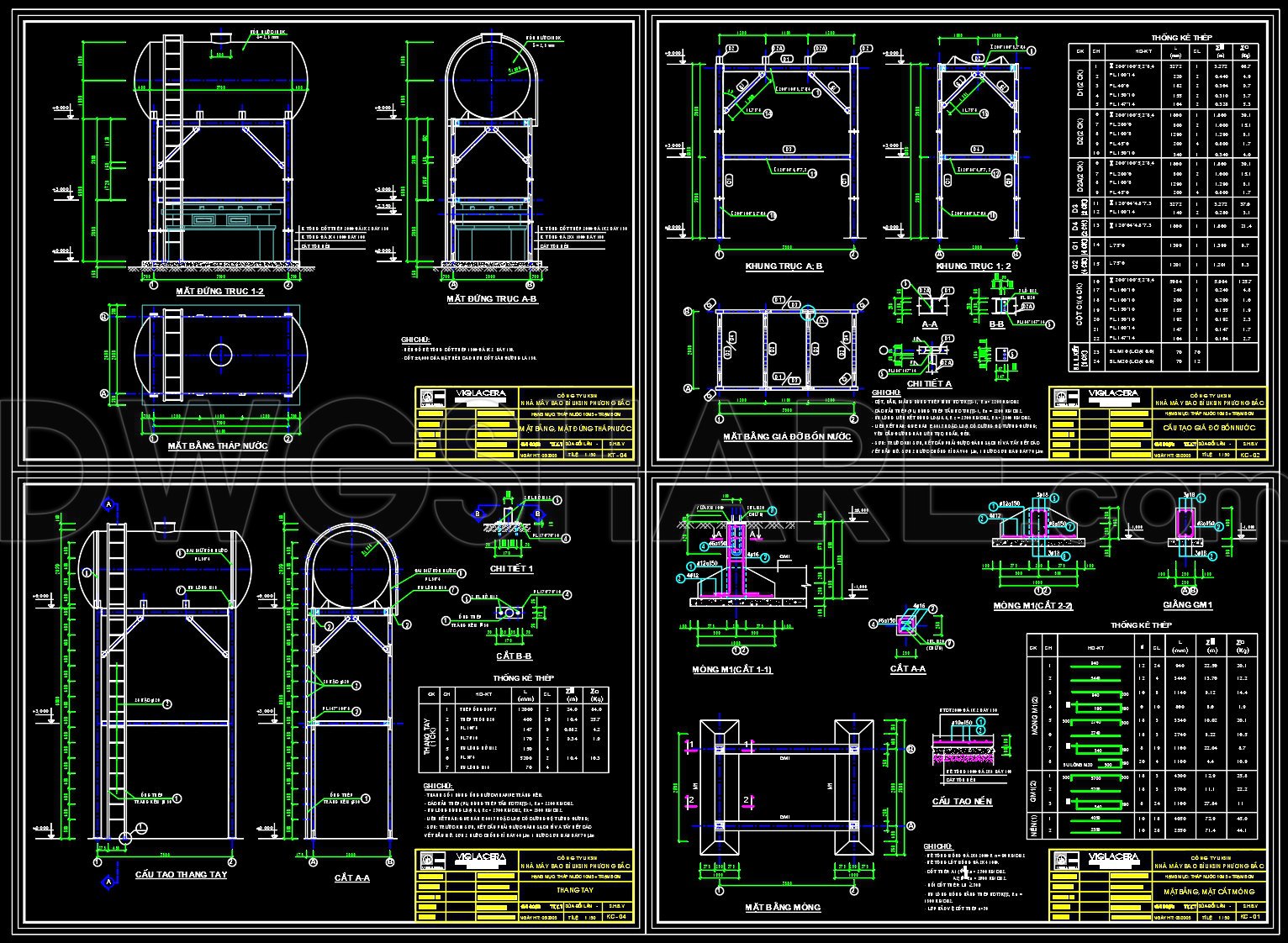
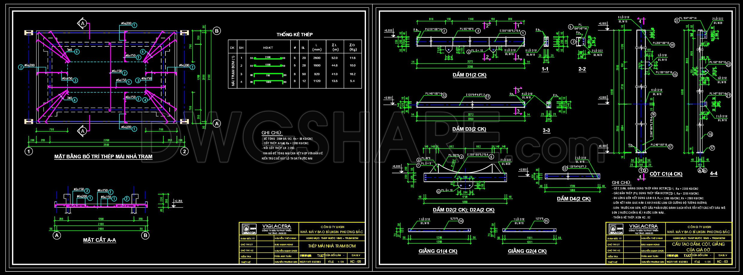
The CAD drawings for the pump house and water tower project present a comprehensive set of structural documents essential for both the design and execution phases in construction. The drawings include detailed architectural floor plans, elevations, sections, and meticulous structural details that provide significant insights into the project’s layout and execution strategies.
These CAD files open with a functional floor plan layout that highlights the spatial arrangement within the pump house, exhibiting precise grid lines and dimensions necessary for accurate spatial planning. This floor plan serves as a critical tool for architects in the design development phase, allowing them to visualize the spatial organization and functionality of the pump house. The use of grid parameters and level markers effectively aids in maintaining dimensional accuracy throughout the design process.
Following the floor plans, the elevations and sections offer vertical insights into the structure, detailing how different parts of the pump house and water tower relate to one another in height and structure. These are invaluable for construction teams as they depict the vertical alignment and design intent, helping in the coordination of real-world construction tasks. Elevations also provide a clear visualization of the exterior finishes and proportions, crucial for facade detailing.
The drawing set also boasts detailed structural drawings. These play a pivotal role in conveying the specifications for load-bearing elements and the construction of the pump house’s core structural components. The clarity in steel reinforcement specifications, noted meticulously, ensures that structural integrity is maintained and checked at every phase by construction supervisors.
The value offered by these CAD drawings is highlighted by their high technical accuracy and flexibility. They are easily modifiable, which is particularly beneficial for iterative design processes and unexpected site-specific changes. Interior designers can leverage these documents as they prepare supplemental technical details or develop custom interior layouts tailored to the mechanical equipment housed within facilities like pump rooms.
Moreover, these drawings are shared freely, extending their utility to a broader audience. They are ideal as a design reference, invaluable for study and research, and serve as a foundational basis for technical drawing development in similar projects. The ease of access to such detailed documentation enhances design understanding and aids in cost optimization, ultimately leading to reduced errors during the construction phase.
I also recommend downloading other Uncategorized CAD drawings for your project reference.
- File format: .DWG
- Size: 1 MB
- Source: DWGshare
- AutoCAD platform 2018 and later versions. For downloading files there is no need to go through the registration process
If you find our work useful, your support would mean a lot and help us grow even better.DONATE
Related posts
8.Urban Lighting Design CAD Blocks
239. 3-Story Modern House Electrical CAD Drawings 11.7m × 7.5m
42. CAD drawings for detailed electrical and plumbing designs for a 4-story townhouse with dimensions of 6m x 14.5m
195. Complete Residential Water Supply and Drainage System CAD Drawings DWG
51. CAD drawings detailing the design of water supply and drainage systems for a 3-story townhouse 6m x 15m
46. CAD drawings for detailed plumbing designs for a 4-story townhouse with dimensions of 8m x 17m
257. Complete Electrical Plans for a 3-Story House – Power Supply & Installation Details
504. CAD Drawings Detailing the Design of Water Supply and Drainage Systems for a 3-Story Townhouse
690. Mechanical Escalator Structural Details CAD DWG – Free Download