
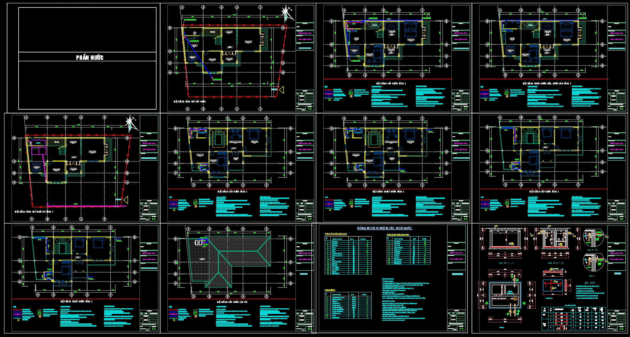
321. House Plumbing System CAD Drawings with Water Supply, Drainage and Installation Details
The House Plumbing System CAD Drawings provide a comprehensive collection of technical details essential for anyone involved in architectural design, construction, or plumbing engineering. These CAD DWG files focus on illustrating the water supply, drainage, and installation processes within residential settings, delivering high-resolution insights into the mechanical systems that support modern homes.
Beginning with the functional floor plan layout, these drawings meticulously map out the entire plumbing infrastructure of a house. These plans reveal the specific routing of water pipes, drainage lines, and related installations, thus serving as a crucial tool for architects and construction teams during the design and development phases. Key components such as water mains, valve placements, and sanitary fixtures are carefully delineated, offering precise guidance for installation and future maintenance tasks.
The elevations and sections are integral in illustrating vertical layouts and spatial arrangements. These drawings offer a visual breakdown of the plumbing system relative to the building’s structural and architectural elements. Elevations provide insights into the vertical positioning of pipes and vents, ensuring alignment with construction codes and enhancing reliability. Sections allow for detailed examination of pipe sizes, installation techniques, and materials, which are critical for the engineering verification process.
For more specific installation insights, the construction detail drawings include exhaustive depictions of joints, connections, and fittings within the plumbing system. These detailed views are essential for plumbers and contractors, providing clear instructions on coupling methods, pressure specifications, and equipment compatibility. The availability of grid lines, dimensions, and level markers further enrich these technical drawings, enabling accurate on-site interpretation and execution.
The house plumbing system drawings are not merely static representations; their high technical accuracy and adaptability in AutoCAD make them invaluable resources. They facilitate seamless modifications tailored to specific project needs, enhancing coordination across design and construction phases. This adaptability reduces errors and contributes to cost optimization, ultimately improving workflow efficiency and project outcomes.
Ultimately, these CAD DWG files are generously provided for free, offering an invaluable resource for architects, interior designers, and researchers alike. They serve as a reliable base for developing further technical drawings and are perfect for educational purposes or as a starting point for innovative design solutions in residential plumbing systems.
I also recommend downloading other Mechanical, Electrical CAD drawings for your project reference.
- File format: .DWG
- Size: 1 MB
- Source: DWGshare
- AutoCAD platform 2018 and later versions. For downloading files there is no need to go through the registration process
If you find our work useful, your support would mean a lot and help us grow even better.DONATE
Related posts
242. Complete 3-Story House Plumbing CAD Drawings
209. Water Supply & Drainage CAD Drawings for Apartment Building (DWG)
271. Complete Residential ELV Design – Low-Voltage, Telecom & Network Plans DWG
305. CAD drawings detailing the design of water supply and drainage systems for a 2-story townhouse
158. 4-Storey Townhouse Plumbing CAD Drawing Free Download
125. Free Download 3-Story Townhouse Electrical CAD Drawings – Complete Layout Design
285. Residential Water Supply & Drainage Plans – Plumbing System Layout DWG
20.Site Office and Administration Lighting and Power CAD
201. 3-Story House Water Supply & Drainage Drawings (DWG)